Eneral, Etup, Page 10 o – Vertex Standard FT-1000MP User Manual
Page 12: Ntenna, Onsiderations, Djusting, Ront, Emory, Ackup, Coaxial cables (assumes 50
Page 10
O
PERATING
M
ANUAL
A
NTENNA
C
ONSIDERATIONS
Loss figures are approximate; consult cable manufac-
turers’ catalogs for complete specifications.
Loss figures can increase significantly if high SWR is
present on the transmission line.
A
DJUSTING
THE
F
RONT
F
EET
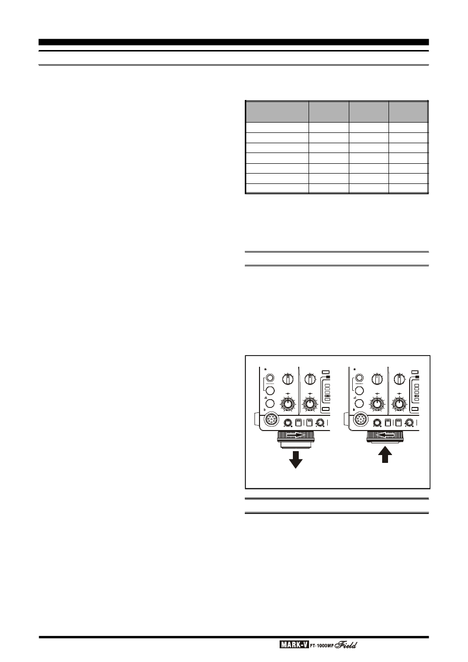
The two front feet of the MARK-V FT-1000MP
Field
can be set in either of two positions. By turning the
knurled ring around a (retracted) foot clockwise, the
middle of the foot will extend about one centimeter.
Turn the ring as far as it will go (about ¼-turn) to lock
the extended foot in place. To retract an extended foot,
turn the knurled ring counterclockwise ¼-turn while
pressing on the center of the foot.
G
ENERAL
S
ETUP
M
EMORY
B
ACKUP
The memory BACKUP switch on the rear panel is
turned on at the factory, allowing VFO and memory
data to be retained while power is off. Backup current
is miniscule, so it is not necessary to turn the BACKUP
switch off unless the transceiver is to be stored for an
extended period.
After five or more years of operation the transceiver
may fail to retain memories, at which time the lithium
battery should be replaced. Contact your dealer for
replacement of the battery; for instructions on how to
do so yourself, see page 114.
Loss in dB per 30m (100 feet)
for Selected 50
W
Coaxial Cables
(Assumes 50
W
Input/Output Terminations)
(To Retract)
(To Extend)
The MARK-V FT-1000MP
Field is designed for use
with any antenna system providing a 50
W resistive
impedance at the desired operating frequency. While
minor excursions from the 50
W specification are of no
consequence, the transceiver’s Automatic Antenna
Tuner may not be able to reduce the impedance mis-
match to an acceptable value if the Standing Wave
Ratio (SWR) present at the Antenna jack is greater
than 3:1. Among the undesirable consequences that
high SWR may produce are:
r The transceiver’s power amplifier protection circuitry
will reduce power if the Automatic Antenna Tuner is
unsuccessful in reducing the SWR.
r Even if the Automatic Antenna Tuner successfully
normalizes the impedance presented to the radio,
feedline losses will escalate rapidly with increasing
SWR at the higher operating frequencies, especially
28 MHz.
r Although high SWR itself does not cause feedline
radiation, the sudden onset of high SWR may well
indicate a mechanical failure in a matching device,
leading to an electrical condition which may cause
excessive feedline radiation, which can cause in-
terference to nearby home-entertainment devices.
Every effort should, therefore, be made to ensure
that the impedance of the antenna system utilized with
the MARK-V FT-1000MP
Field be as close as possible
to the specified 50
W value.
Any antenna to be used with the MARK-V FT-
1000MP
Field must, ultimately, be fed with 50 W co-
axial cable. Therefore, when using a “balanced” an-
tenna such as a dipole, remember that a balun or other
matching/balancing device must be used so as to en-
sure proper antenna performance.
The same precautions apply to any additional (re-
ceive-only) antennas connected to the RX ANT jack; if
your receive-only antennas do not have an impedance
near 50
W at the operating frequency, you may need to
install an external antenna tuner to obtain optimum
performance.
Use high-quality 50
W coaxial cable for the lead-in
to your MARK-V FT-1000MP
Field transceiver. All ef-
forts at providing an efficient antenna system will be
wasted if poor quality, lossy coaxial cable is used.
Losses in coaxial lines increase as the frequency in-
creases, so a coaxial line with only 0.5 dB of loss at 7
MHz may have 2 dB of loss at 28 MHz. For reference,
the chart in the next column shows approximate loss
figures for typically-available coaxial cables frequently
used in amateur radio installations.
Cable Type
RG-58A
RG-58 Foam
RG-8X
RG-8A, RG-213
RG-8 Foam
Belden® 9913
RG-17A
Loss:
2 MHz
0.55
0.54
0.39
0.27
0.22
0.18
0.88
Loss:
15 MHz
1.75
1.50
1.07
0.85
0.65
0.50
0.30
Loss:
28 MHz
2.60
2.00
1.85
1.25
0.88
0.69
0.46
KEY
MIC
A
B
PHONES
AGC
MIC
AF
GAIN
RF
GAIN
PROC
FAST
0
6
12
18
dB
( )
OFF
SLOW
AUTO
ATT
240
120
60
IPO
OFF
APF
APF
RF PWR
MONI
SUB AF
PROC
ED
KEY
MIC
A
B
PHONES
AGC
MIC
AF
GAIN
RF
GAIN
PROC
FAST
0
6
12
18
dB
( )
OFF
SLOW
AUTO
ATT
240
120
60
I P O
OFF
APF
APF
RF PWR
MONI
SUB AF
PROC
ED