Ront, Anel, Ontrols – Vertex Standard FT-1000MP User Manual
Page 24: Page 22 o, Power button, Mox & vox buttons, Agc selector knob, Phones jack, Key jack, Mic jack
Page 22
O
PERATING
M
ANUAL
F
RONT
P
ANEL
C
ONTROLS
This chapter describes each control and connector on the MARK-V FT-1000MP
Field. You can just glance
through it quickly now, but some of the descriptions will be more meaningful if you take the time to read them in
detail now. If questions arise later while proceeding through the operation chapter, you can return to this chapter
with the set powered up for control knob clarification. Some controls and switches are disabled under certain
conditions.
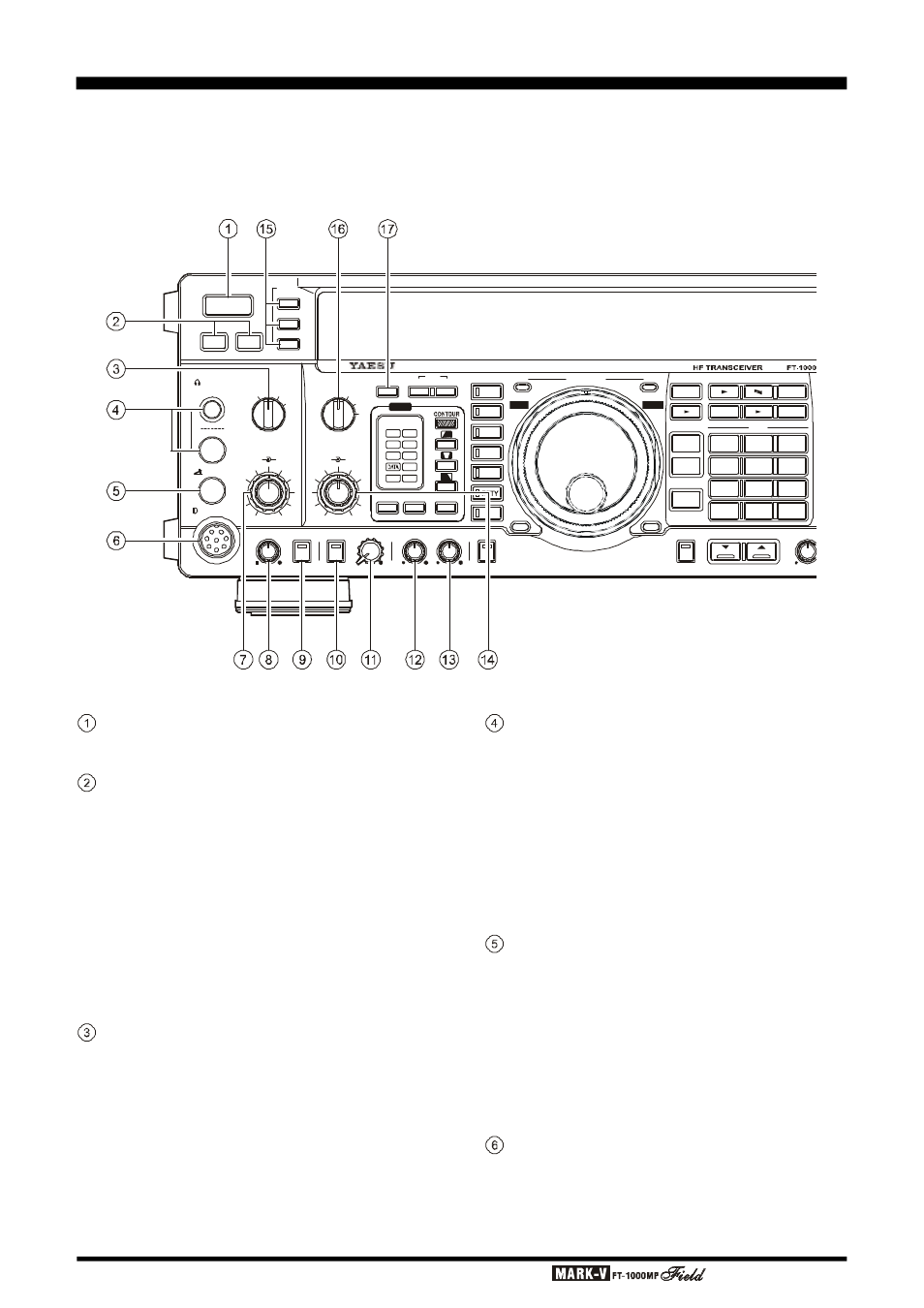
POWER Button
This button turns the transceiver on and off.
MOX & VOX Buttons
[MOX] may be used in place of a microphone PTT
switch or footswitch to activate the transmitter, when
depressed. It must be in the undepressed position for
reception.
[VOX] enables automatic voice-actuated transmit-
ter switching in the SSB, AM and FM modes, and “semi-
break-in” keying in CW mode. The controls affecting
VOX operation are located in the top access panel.
Menu Selection 7-5 sets the receiver recovery time dur-
ing semi-break-in CW operation.
AGC Selector Knob
Selects main receiver Automatic Gain Control de-
cay time for most comfortable reception, or disables
receiver AGC (off). Normally this switch is set to the
“AUTO” position. Strong signals will cause distortion if
this selector is set to “OFF.”
KEY
MIC
POWER
MOX
VOX
METER
IC/SWR
ALC/COMP
VCC/MIC
A
B
PHONES
AGC
MIC
AF
GAIN
RF
GAIN
PROC
FAST
0
6
12
1 8
dB
( )
OFF
SLOW
AUTO
ATT
240
120
60
A
IPO
A/B
ANT
R X
RX
MAIN VFO-A
TX
RCL
7
3
QMB
BAND
STO
DUAL
M A
A B
M CK
A M
M GRP
RPT
A B
VFO/
MEM
FAST
LOCK
OFF
B
C
D
OFF
OFF
APF
APF
NR
LSB
USB
CW
AM
FM
PKT
CLASS-A
AF REV
SQL
SUB S
MONI
RF PWR
MONI
SUB AF
PROC
NR
1.8
1
10
4
21
7
SUB
D E
3.5
2
14
5
24.5
8
29
0
1 8
6
2 8
9
ENT
DOWN
U P
VRF
IDBT
EDSP
PHONES Jack
A ¼-inch and 3.5 mm, 3-contact jack accept either
monaural or stereo headphones with 2- or 3-contact
plugs. When a plug is inserted, the loudspeaker is dis-
abled. With stereo headphones such as the optional
YH-77STA, you can monitor both receiver channels at
the same time during dual reception. In this case, the
headphone HP controls (page 32) beneath the top ac-
cess panel adjust the default levels for mixed, sepa-
rate, or monaural headphone operation.
KEY Jack
This ¼-inch, 3-contact jack accepts a CW key or
keyer paddles (for the built-in electronic keyer), or out-
put from an external electronic keyer. You cannot use
a 2-contact plug in this jack (to do so produces a con-
stant “key down” condition). Pinout is shown on page
4. Key up voltage is 5 V, and key down current is 0.5
mA. There is another jack with the same name, con-
nected in parallel with this jack, on the rear panel.
MIC Jack
This 8-pin jack accepts input from the MH-31
B8D
Microphone. MIC connector pinout is shown on page
4. Proper microphone input impedance is 500 ~ 600
Ohms.