G-link, Connection, Terminal on the tv – Toshiba Integrated High Definition DLP 62HM15 User Manual
Page 25: The g-link, Cable from the cable box to the g-link, Terminal to receive the tv guide on screen, Cable from the vcr to the g-link, Terminal to use the tv guide on screen, System’s recording features, Plug the g-link
25
Chapter 2: Connecting your TV
62HM15
Copyright © 2005 TOSHIBA CORPORATION. All rights reserved.
After you connect your devices to the TV, you will need to connect the G-LINK
®
cable (either of the dual-wand IR blaster cables
included with your TV) from your VCR and Cable box (if applicable) to the G-LINK
®
terminal on the TV.
Note: TV Guide On Screen
®
program data is available through the ANT-1 and ANT-2 antenna inputs and also
through the VIDEO 1 inputs if you have a cable box connected to VIDEO 1. TV Guide On Screen
®
program
data is not available through any other inputs on this TV. See the connection information on pages 13–25.
The G-LINK
®
connection is necessary to enable the following features of your TV Guide On Screen
®
system:
• If you have a Cable box, you need to connect the G-LINK
®
cable from the Cable box to the G-LINK
®
terminal to receive the
TV Guide On Screen
®
system’s program listings for your Cable service.
• If you have a VCR, you need to connect the G-LINK
®
cable from the VCR to the G-LINK
®
terminal to use the TV Guide
On Screen
®
system’s recording features.
G-LINK
®
connection
This connection is necessary for the TV Guide On Screen
®
system to work with your cable box to receive program listings and to
enable TV Guide On Screen
®
recording features with your VCR.
Note: This connection is not necessary for AVHD or D-VHS recording devices. See pages 23 and 49 for further details.
TheaterNet
OUT
IN
AUDIO
IN
S-VIDEO
VIDEO 1
VIDEO 2
L
R
OUT 1
G-LINK
HDMI IN
DIGITAL
AUDIO OUT
ANT (75 )
ANT1
(CABLE)
ANT2
CableCARD™
COLOR
STREAM
HD-1
COLOR
STREAM
HD-2
VAR
AUDIO
R
L
TheaterNet
OUT 2
1
2
S-VIDEO
IEEE1394
EJECT
L/
MONO
AUDIO
VIDEO
R
L/
MONO
AUDIO
VIDEO
R
L/
MONO
AUDIO
VIDEO
R
P
B
P
R
Y
L
AUDIO
R
P
B
P
R
Y
L
AUDIO
R
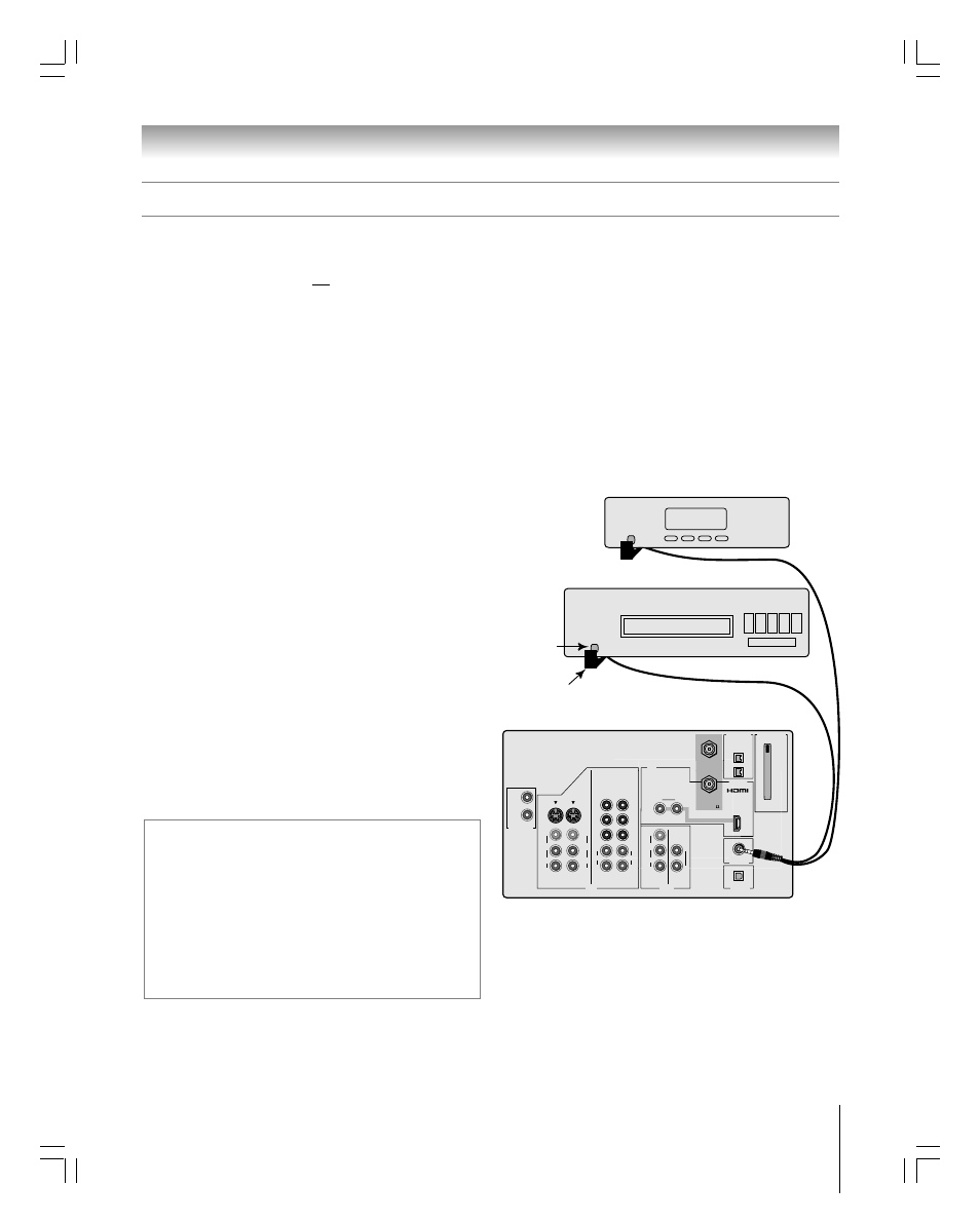
Back of TV
Front of VCR
Front of Cable box
Infrared
sensor
G-LINK
®
(IR blaster) cable wand
(approx. 1 inch from device)
TheaterNet
*
If you cannot locate the device’s infrared sensor:
1. Turn OFF the device.
2. Starting at the lower left corner of the device, place the end of the
device’s remote control (with the infrared emitter) so it touches the
front of the device and press POWER. (Do not use the TV’s remote
control for this step.)
3. If the device turns on, the place the remote control touched the
device is the location of the sensor.
4. If the device does not turn on, move the remote control slightly to the
right and press POWER again.
5. Repeat step 4 until you locate the device’s infrared sensor.
To connect to the G-LINK
®
terminal:
1. Locate the infrared sensor on the front of your VCR or
Cable box. The sensor is marked on some devices.*
2. Align one of the G-LINK
®
(IR blaster) cable’s wands about
1 inch away from the infrared sensor on the front of the
VCR and attach it using double-sided mounting tape.
If you have a Cable box, attach the other wand in a similar
manner. (See illustration at right.)
Note: If you do not have a Cable box, coil the second wand
with a rubber band and leave it behind the TV.
3. Plug the G-LINK
®
(IR blaster) cable’s plug into the TV’s
G-LINK
®
terminal.
For details on setting up the TV Guide On Screen
®
system:
See Chapter 5.
For details on using the TV Guide On Screen
®
interactive
program guide:
See Chapter 7.
#01E012-025_62HM15
5/24/05, 6:17 PM
25
Black