Connecting a camcorder, Recording features: 1. connect the g-link, System – Toshiba Integrated High Definition DLP 62HM15 User Manual
Page 13: You will need: one set of standard a/v cables
13
Chapter 2: Connecting your TV
62HM15
Copyright © 2005 TOSHIBA CORPORATION. All rights reserved.
TheaterNet
OUT
IN
AUDIO
AUDIO
IN
S-VIDEO
VIDEO 1
VIDEO 2
OUT 1
INK
INK
DIGITAL
AUDIO OUT
ANT1
CableCARD™
COLOR
STREAM
HD-1
COLOR
STREAM
HD-2
TheaterNet
OUT 2
1
S-VIDEO
IEEE1394
EJECT
L/
MONO
AUDIO
VIDEO
R
L/
MONO
AUDIO
VIDEO
R
P
B
P
R
Y
L
AUDIO
R
IN from ANT
VIDEO AUDIO
OUT to TV
CH 3
L
R
L
R
CH 4
IN
OUT
TheaterNet
OUT
OUT
IN
Signal splitter
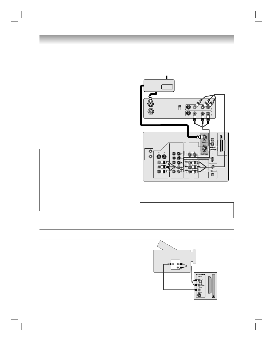
You will need:
one signal splitter
three coaxial cables
two sets of standard A/V cables
• For better picture performance, if your VCR has S-video, use an
S-video cable (plus the audio cables) instead of the standard video
cable. However, do not connect both types of video cables to
VIDEO 1 (or VIDEO 2) at the same time or the picture
performance will be unacceptable.
• If you have a mono VCR, connect L/MONO on the TV to your
VCR’s audio out terminal using the white audio cable only.
To view the antenna or Cable signal:
Select the ANT 1 video input source on the TV.*
To view the VCR:
Turn ON the VCR. Select the VIDEO 1 video input source
on the TV.*
Connecting a VCR and antenna or Cable TV (no Cable box)
From Cable TV or antenna
Stereo VCR
TV
The unauthorized recording, use, distribution, or revision of television
programs, videotapes, DVDs, and other materials is prohibited under the
Copyright Laws of the United States and other countries, and may subject
you to civil and criminal liability.
To use the TV Guide On Screen
®
recording features:
1. Connect the G-LINK
®
cable according to the instructions
on page 25.
2. Make sure the VCR is connected to the A/V OUT
terminals on the TV (see illustration).
3. Set the VCR to the appropriate line input (refer to your
VCR owner’s manual for details), and then turn OFF the
VCR.
4. See Chapter 5 for details on setting up the TV Guide
On Screen
®
system.
5. See Chapter 7 for details on using the TV Guide
On Screen
®
system.
Connecting a camcorder
VIDEO
AUDIO
OUT
L
R
You will need:
one set of standard A/V cables
• For better picture performance, if your camcorder has S-video, use an
S-video cable (plus the audio cables) instead of the standard video cable.
Do not connect both an S-video cable and a standard video cable to VIDEO
3 at the same time or the picture performance will be unacceptable.
To view the camcorder video:
Select the VIDEO 3 video input source on the TV.*
VIDEO 3 inputs on TV right side panel
Camcorder
_____________
*
To select the video input source, press INPUT on the remote control (see page 66).
To program the TV remote control to operate other devices, see Chapter 3.
Note: The VIDEO/AUDIO OUT terminals output signals from the
ANT 1, ANT 2, VIDEO 1, VIDEO 2, and VIDEO 3 terminals when the
appropriate input mode is selected.
#01E012-025_62HM15
5/24/05, 6:16 PM
13
Black