Front panel leds, Rear panel, Front panel leds -12 – TANDBERG High Definition Professional Recevier/Decoder TT1280 User Manual
Page 20: Rear panel -12, Figure 1.7: front panel controls -12, 3 front panel leds, 4 rear panel
Introduction
Page 1-12
Reference Guide: TT128x High Definition Professional Receiver/Decoder
ST.RE.E10141.5
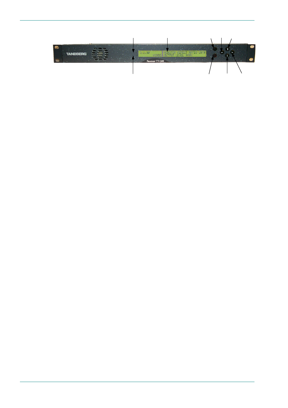
Figure 1.7: Front Panel Controls
1.6.3
Front Panel LEDs
Figure 1.7 shows the location of the LEDs on the front panel. The LEDs
indicate the equipment status as follows:
The red ALARM LED is used to indicate an IRD fault condition, e.g. a
missing or faulty input signal. It should be off for correct operation,
although it may be lit briefly during power-up.
The green LOCK LED is used to indicate that the IRD is locked to a
Transport Stream when lit, and indicates correct conditions and correct
system functioning.
1.6.4 Rear
Panel
Inputs and outputs to the unit are taken via the rear panel. Connector
descriptions are given in Chapter 2, Installing the Equipment and
Chapter 6, Options.
LCD display
Save
Edit
Up
Down
Left
Right
Alarm LED
Lock LED