Cutter module (b-4205-qm) – Toshiba B-570 User Manual
Page 22
3-3
EM18-33010A
3. INSTALLATION PROCEDURE FOR THE OPTIONAL EQUIPMENT
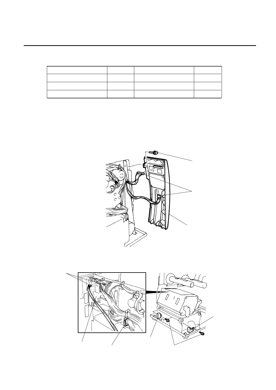
5.
Unclamp and disconnect the connector for the strip sensor from CN5 on the CPU PC board.
6.
Remove the SM-4x6B screw to detach the strip sensor (LED)/(Tr).
Fig. 3-3
Fig. 3-4
3.2 CUTTER MODULE (B-4205-QM)
3.2 CUTTER MODULE (B-4205-QM)
NOTE: For the B-570 series, the take-up/cutter harness enclosed with the B-4205-QM is not used but
the take-up harness connected to CN2 on the PWM PC board.
1.
Remove the top cover and left side cover. (See Fig. 2-1.)
2.
Remove the I/F PC board. (See Fig. 2-2.)
3.
Remove the front plate. (See Fig. 2-6.)
4.
Remove the screw (SM-4x8B) and two connectors to detach the operation panel.
Description
Q’ty/Unit
Description
Q’ty/Unit
Cutter Unit
1
Cutter Attaching Screw
2
Cutter Cover
1
Screw (FL-4x6)
1
Take-up/Cutter Harness
1
Cleaner
1
Screw (SM-4x8B)
Connector
Operation Panel
Connector (CN5)
CPU PC Board
Clamp
Strip Sensor (Tr)
Screw (SM-4x6B)
Strip Sensor (LED)
- e-STUDIO222cp (16 pages)
- e-STUDIO382p (22 pages)
- Copier (78 pages)
- e-Studio Imaging 5520c (288 pages)
- multifunctional digital color systems e-STUDIO4540C (282 pages)
- B-852 Advance (2 pages)
- GA-1121 (118 pages)
- 720T (8 pages)
- 305 (168 pages)
- TEC EO1-32004 (94 pages)
- TEC DRJST-51 (19 pages)
- MULTIFUNCTIONAL DIGITAL COLOR SYSTEMS 2830C (178 pages)
- B-SP2D (50 pages)
- R-TH10 (86 pages)
- B-682-QP (157 pages)
- B-680-QQ (32 pages)
- e-STUDIO 281C (8 pages)
- TEC EO1-33027E (122 pages)
- MULTIFUNCTIONAL DIGITAL COLOR SYSTEMS e-STUDIO5520C (210 pages)
- 7FM03281000 (34 pages)
- GD-1270 (120 pages)
- ESTUDIO 230L (382 pages)
- 520 (7 pages)
- TEC EM1-33043D (46 pages)
- B-EP2DL (28 pages)
- TRST-A15 SERIES (31 pages)
- TEC B 452 (184 pages)
- TEC EO1-33016E (34 pages)
- B-670-QQ (34 pages)
- REMOTE RECEIPT PRINTER TRST-A00 (35 pages)
- e-STUDIO Printer/Fax/Scanner/Copier (4 pages)
- 282 (48 pages)
- B-480-QP (170 pages)
- B-450-QQ (28 pages)
- B-480-QQ (30 pages)
- B-SA4TP SERIES (114 pages)
- TEC EO1-13016 (24 pages)
- B-450-HS-QQ (34 pages)
- E.STUDIO 603 (216 pages)
- e-STUDIO 170F (244 pages)
- B-SA4 (2 pages)
- TEC EM1-33039E (34 pages)
- B-852 (2 pages)
- B-570 SERIES (158 pages)