1 displaying details of an item monitored – Toshiba RKP004Z User Manual
Page 27
7. Operation in Status Monitor Mode
7-2
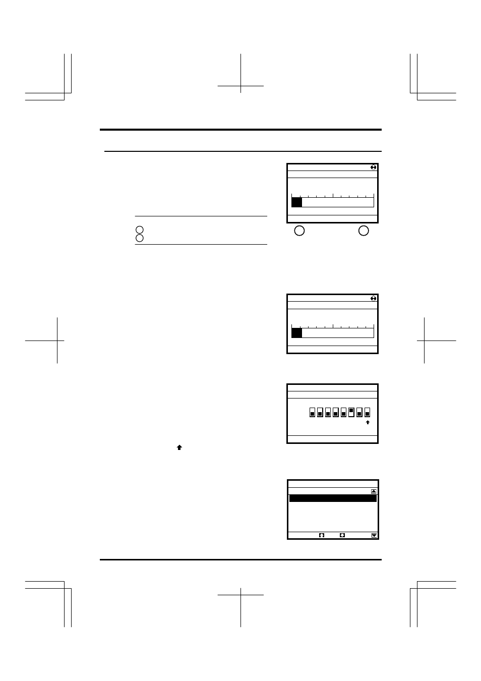
7. 1 Displaying details of an item monitored
1
Select/confirm the desired item using the
control dial.
(Ex. Select/confirm “Output current”)
The monitor window of the item selected appears.
* Depending on the item selected, no monitor
window may be displayed.
Functions of function keys
: Brings you to the Top View Mode.
: Brings you to the Parameter Setup Mode.
How to use monitor windows
Monitor windows can be broadly classified under the
following three types.
This type of window displays an analog value,
such as an output frequency, output current or
output voltage. (Ex. “Output current”)
It displays the current value both numerically and
in a graph form.
In addition, the minimum allowable value (min)
and the maximum allowable value (max) are also
displayed at the bottom of the window.
This type of window displays input/output terminal
information and a life alarm in a graph form. (Ex.
“Input terminal : S4, S3...R, F”)
It displays the ON/OFF status of each terminal
signal and the ON/OFF status of an alarm signal in
a graph form.
If the arrow
is moved to a terminal or alarm
symbol, the name of the function assigned to the
terminal or the name of the alarm is displayed.
This type of window displays detailed trip
information. (Ex. Past trip # 1 (latest))
It displays the conditions under which the inverter
was operated at the occurrence of tripping.
Status Monitor Mode
Input terminal 1 : S4,S3…R,F
ON
OFF
Forward run
Top
Prm
S4 S3 S2 S1 RES
ST R F
Past trip # 1 (latest)
E :Emergency stop
Sequence number
1
Output frequency
25.0Hz
Rotative direction
FWD
Frequency reference
30.0Hz
Output current
40%
Top
Prm
Output current
min=0 max=185
Top
Prm
22%
Status Monitor Mode
Output current
min=0 max=185
Top
Prm
22%
Status Monitor Mode
* This illustration shows the
information displayed when the
LCD panel is connected to an
VF-AS1 inverter.
F1
F4
F1
F4