TDK GENESYS 750W HALF RACK User Manual
Page 59
83-507-5002 Rev. B
51
NOTE
Tx and Rx are used for RS232 communication. Txd +/- and Rxd +/- are used for RS485
communication. Refer to RS-232 and RS-485 cabling and connection details.
2. There are two Remote modes:
1. Remote:
In this mode, return to local can be made by the front panel REM/LOC or
via serial port command RMT 0. Set the unit into Remote mode via serial
port RMT 1 command.
2. Local Lockout: In this mode the unit can be returned to Remote mode via the serial port
RMT 1 command or by turning off the AC power until the display turns off,
and then turn it to on again. In local Lockout mode, the front panel
REM/LOC button is not active. Set the unit into Local Lockout mode via se-
rial port RMT 2 command.
7.2.6 RS232/RS485 port in Local mode
When the power supply is in Local mode, it can receive queries or commands. If a query is re-
ceived, the power supply will reply and remain in Local mode. If a command that affects the out-
put is received, the power supply will perform the command and change to Remote mode.
Serial commands may be sent to set the status registers and read them while the unit is in Local
mode. If the Enable registers are set (refer to Section 7.11) the power supply will transmit SRQ’s
while in Local.
7.2.7 Front panel in Remote mode
Front panel control in Remote mode is Disabled except for:
1. PREV: use to preview the Voltage and Current setting.
2. OVP/UVL: use to preview the OVP/UVL setting.
3. LOC/REM: use to set the unit into Local mode.
In Local Lockout mode, only the PREV and OVP/UVL pushbuttons are active.
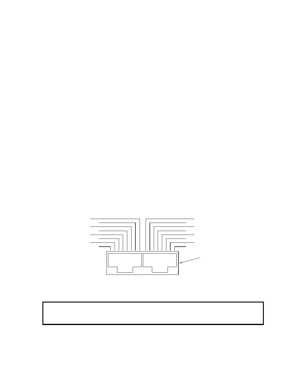
7.3 REAR PANEL RS232/RS485 CONNECTOR
The RS232/RS485 interface is accessible through the rear panel RS232/RS485 IN and RS485
OUT connectors. The connectors are 8 contact RJ-45. The IN and OUT connectors are used to
connect power supplies in a RS232 or RS485 chain to a controller. Refer to Fig. 7-1 for IN/OUT
connectors.
NC
NC
RX
NC
NC
TXD
RXD
TXD
RXD
RXD
TXD
RXD
TXD
SG
SG
-
-
-
-
+
+
+
+
TX
OUT
IN
Fig.7-1: Rear panel J3 IN/OUT connectors pinout
8 7 6 5 4 3 2 1 8 7 6 5 4 3 2 1
Shield
(connector enclosure)