TDK GENESYS 750W HALF RACK User Manual
Page 55
83-507-5002 Rev. B
47
CAUTION
To maintain the power supply isolation and to prevent ground loops, use an
isolated programming source when operating the power supply via remote
analog programming at the J1 connector.
6.4 REMOTE VOLTAGE PROGRAMMING OF OUTPUT VOLTAGE AND OUTPUT
CURRENT LIMIT
Perform the following procedure to set the power supply to Remote Voltage programming:
1. Turn the power supply AC On/Off switch to Off.
2. Set setup switch SW1, positions 1 and 2 to their UP position.
3. Set SW1, position 3 to select the programming voltage range according to Table 6-3.
4. Ensure that SW1, positions 7 and 8 are at their DOWN (default) position.
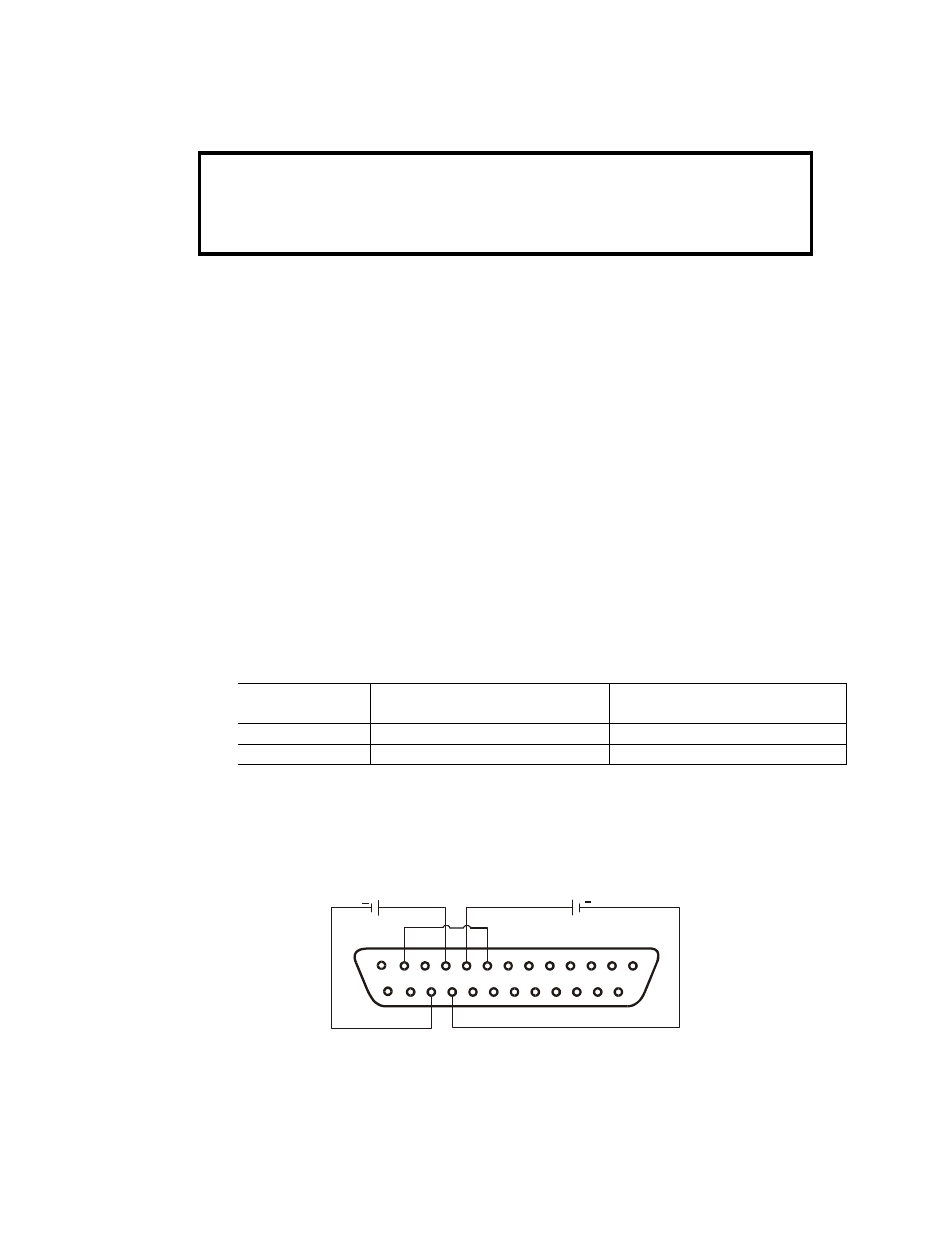
5. Connect a wire jumper between J1-8 and J1-12 (refer to Table 4-4).
6. Connect the programming source to the mating plug of J1 as shown in Fig.6-1. Ob-
serve correct polarity for the voltage source.
7. Set the programming sources to the desired levels and turn the power supply ON. Ad-
just the programming sources to change the power supply output.
NOTES:
1. SW1, positions, 4, 5, 6 and 9 are not required for remote programming. Their settings
can be determined according to the application.
2. The control circuits allow the user to set the Output Voltage and Output Current up to
5% over the model-rated maximum value. The power supply will operate within the ex-
tended range, however it is not recommended to operate the power supply over its
voltage and current rating, and performance is not guaranteed.
SW1-3 setting
Output Voltage programming
VPGM (J1-9)
Output Current programming
IPGM (J1-10)
UP
0-10V
0-10V
DOWN
0-5V
0-5V
Table 6-3: SW1-3 setting and programming range
1
14
13
25
10
12
8
9
23
22
+
+
OUTPUT CURRENT
PROGRAMMING
OUTPUT VOLTAGE
PROGRAMMING
J1 connector, rear panel view
Fig.6-1: Remote voltage programming connection