TDK GENESYS 750W HALF RACK User Manual
Page 37
83-507-5002 Rev. B
29
Table 4-1: Front Panel Controls and Indicators (continued)
Number
Control/Indicator
Description
Section
15
PREV indicator
Green LED, lights when PREV button is pressed
16
FINE button
Voltage and Current Fine/Coarse adjustment control. Op-
erates as a toggle switch. In Fine mode, the VOLTAGE
and CURRENT encoders operate with high resolution and
in Coarse mode with lower resolution (approx. 6 turns).
Auxiliary function: Set units as Master or Slave in Ad-
vanced parallel operation.
5.15.2
17
FINE indicator
Green LED, lights when the unit is in Fine mode.
18
ALARM indicator
Red LED, blinks in case of fault detection. OVP, OTP
Foldback, Enable and AC fail detection will cause the
ALARM LED to blink.
19
AC Power switch
AC On/Off control.
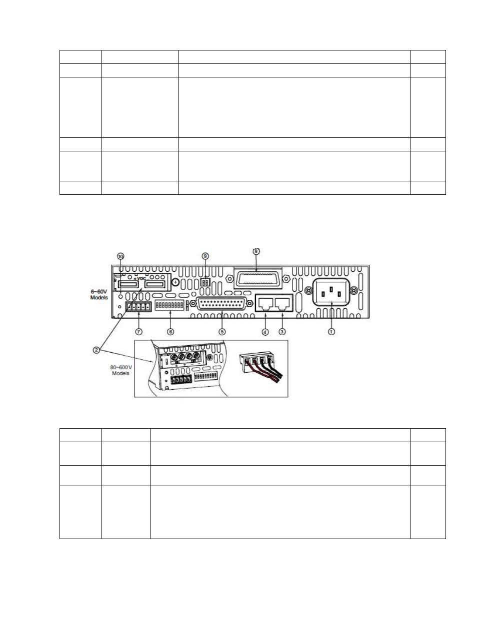
4.3 REAR PANEL CONNECTIONS AND CONTROLS
See Fig.4-2 to review the connections and controls located on the power supply rear panel. Refer
to Table 4-2 for explanations about the rear panel connections and controls.
Fig.4-2: Rear panel connections and controls
Table 4-2: Rear panel connections and controls
Number
Item
Description
Section
1
AC input
connector
Wire clamp connector for 1500W units.
IEC connector for 750W units.
3.7.1
3.7.2
2
DC output
Bus-bars for 6V to 60V models.
Wire clamp connector for 80V to 600V models.
3.9.6
3
Remote-In
connector
RJ-45 type connector, used for connecting power supplies to
RS232 or RS485 port of computer for remote control purposes.
When using several power supplies in a power system, the first
unit Remote-In is connected to the computer and the remaining
units are daisy-chained, Remote-In to Remote-Out.
7.3
7.5