Package contents, Connecting the interface cables, 3 package contents – RAD Data comm ASMi-52 User Manual
Page 34: 4 connecting the interface cables, Figure 2-1. asmi-52 rear panel (plastic enclosure), Figure 2-2. asmi-52 rear panel (metal enclosure)
Chapter 2 Installation and Setup
Installation and Operation Manual
2-2
Connecting the Interface Cables
ASMi-52 Ver. 2.5
Allow at least 90 cm (36 in) of frontal clearance for operation and maintenance
accessibility. Allow at least 10 cm (4 in) clearance at the rear of the unit for signal
lines and interface cables.
The ambient operating temperature of ASMi-52 should be 0° to 50°C (32° to
122°F), at a relative humidity of up to 90%, non-condensing.
2.3 Package Contents
The ASMi-52 package includes the following items:
• One ASMi-52 unit
• Technical documentation CD
• Power connection accessories (depending on which power option was
ordered):
Power cord (VAC) and AC/DC plug (-48 VDC)
Terminal block kit (24 VDC)
• CBL-RJ45/2BNC/E1 adapter cable for unbalanced E1 interface (if ordered)
• RM-33 rack mount kit for the plastic case unit (if ordered)
• RM-35 rack mount kit for the metal case unit (if ordered)
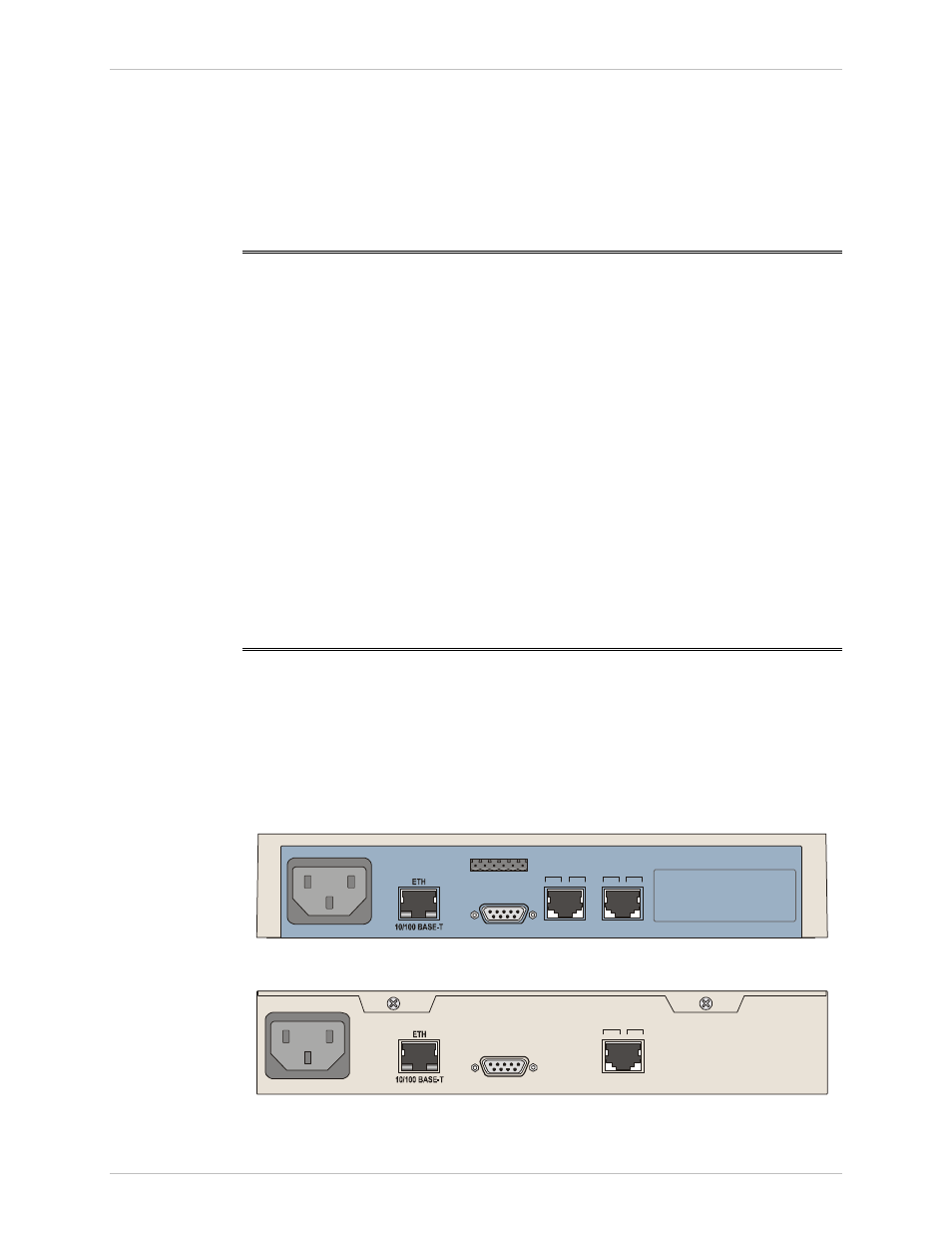
2.4 Connecting the Interface Cables
Figure 2-1
illustrates the rear panel of ASMi-52 in a plastic enclosure with a 4-wire
line interface, E1 DTE interface, user LAN interface, alarm relay port and the
control port.
Figure 2-2
illustrates the rear panel of ASMi-52 in a metal enclosure with a 4-wire
line interface, the user LAN interface, and the control port.
E1/T1
SHDSL
DCE
V.35
CONTROL
ALARM
LINE
B
TX
LINE
A
RX
1
1
4
4
2
2
5
5
ACT
LINK
Figure 2-1. ASMi-52 Rear Panel (Plastic Enclosure)
SHDSL
CONTROL
LINE
B
LINE
A
1
4
2
5
ACT
LINK
Figure 2-2. ASMi-52 Rear Panel (Metal Enclosure)