RAD Data comm ASMi-52 User Manual
Page 132
Appendix A Interface Connector Specifications
Installation and Operation Manual
A-2
DTE Interface Connectors
ASMi-52 Ver. 2.5
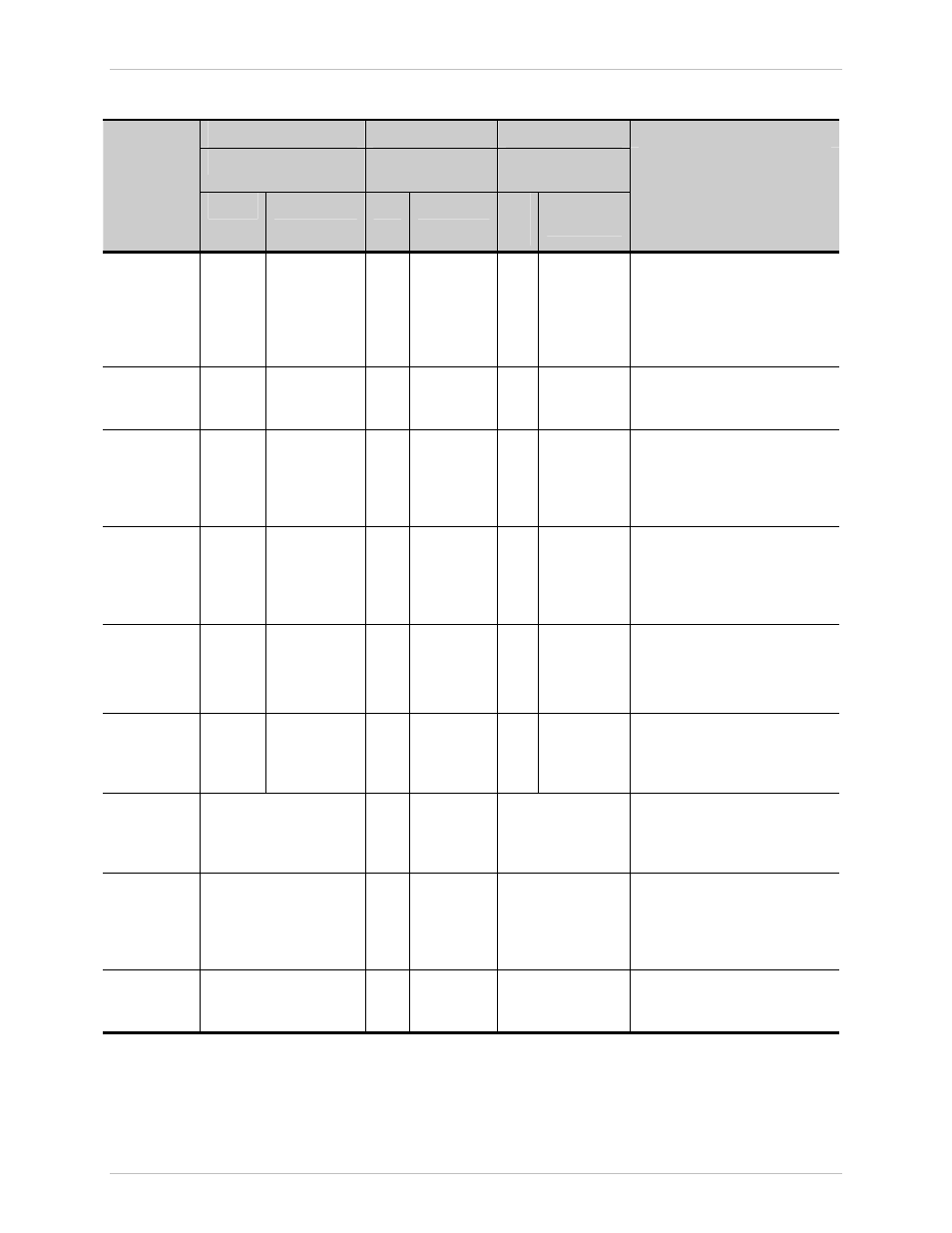
Table A-1. V.35, X.21 and RS-530 Connector Pinouts (Cont.)
V.35
RS-530
X.21
Description
34-Pin
DB-25
DB-15
Signal
Function
Pin
Circuit
Pin
Circuit
Pin
Circuit
(Function)
Data Set
Ready
E DSR
107
6
22
CC(A)
CC(B)
A positive level from ASMi-52
when power is on, and ASMi-52
is (a) not in DIGITAL LOOP
mode, or (b) has not received a
REMOTE LOOPBACK signal
from the remote unit.
Data
Terminal
Ready
H DTR
108
20
23
CD(A)
CD(B)
Not
used
Carrier
Detect
F DCD
109
8
10
CF(A)
CF(B)
5
12
I(A)
I(B)
(Indication)
A positive level from ASMi-52,
except when a loss of the
received signal is detected or
when Data Set Ready is
negative.
External
Transmit
Clock
U
W
SCTE(A) 113
SCTE(B) 113
24
11
DA(A)
DA(B)
7
14
(A)
(B)
A serial data rate clock input
from the data source. Positive
clock translations must
correspond to data
transmissions.
Transmit
Clock
Y
a
SCT(A) 114
SCT(B) 114
15
12
DB(A)
DB(B)
6
13
S(A)
S(B)
(Signal
Timing)
A transmit data rate clock for
use by an external data source.
Positive clock translations
correspond to data translations.
Receive
Clock
V
X
SCR(A)
115
SCR(B)
115
17
9
DD(A)
DD(B)
A receive data rate clock output
used by an external data sink.
Positive clock translations
correspond to data translations.
Local Analog
Loop
L and j
18
LL
A control signal input, which,
when on, sets ASMi-52 into
Local Analog Loopback (V.54
Loop 3).
Remote
Digital Loop
N and h
21
RL
A control signal input which,
when on, commands
ASMi-52 to send a remote
Loopback command (V.54 Loop
2) to the remote ASMi-52.
Test
Indicator
n and k
25
TM
A Control Signal output from
ASMi-52; positive during any
test mode.