Renesas Emulation Pod M37641T2-RPD-E User Manual
Page 34
( 32 / 68 )
(2) Changing the Oscillator Circuit in the Emulation Pod
Oscillator circuit boards for 24 MHz (for XIN) and 32.768 kHz (for XCIN) are mounted in this
product. To use the emulation pod at a frequency other than 24 MHz or 32.768 kHz, build the desired
oscillator circuit on the included oscillator circuit board OSC-2 (bare board) and replace the board
installed in the emulation pod when shipped from the factory.
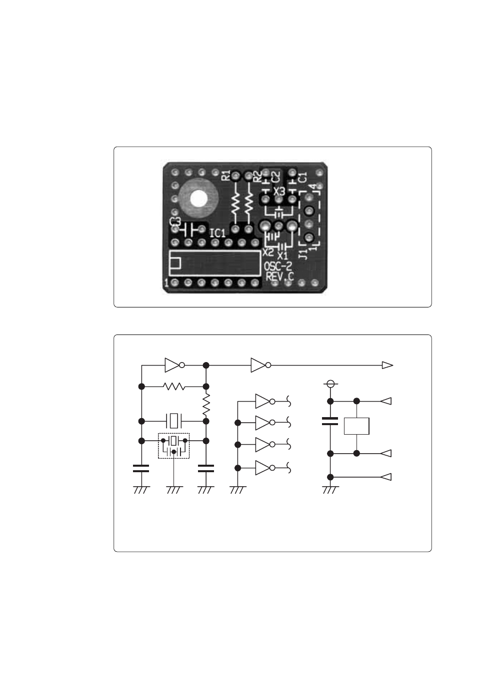
Figure 3.12 shows a view of oscillator circuit board OSC-2 (bare board) and where connector pins
are located. Figure 3.13 shows the circuitry of oscillator circuit board OSC-2 (bare board). Use the
number of oscillator circuits recommended by the oscillator manufacturer.
Figure 3.12 External view of oscillator board OSC-2 and connector pin assignments
J1-4: GND
Figure 3.13 Circuit of oscillator board OSC-2
J1-3: Oscillator output
J1-2: GND
J1-1: Vcc (5 V)
* X1: 5.08-mm-pitch 2-pin oscillator
IC1: Inverter (Unbuffer)
*
X2: 2.54-mm-pitch 2-pin oscillator
*
X3: 2.54-mm-pitch 3-pin oscillator
IC 1
R 1
C2
C 1
X 1 ,X 2
C LK
V cc
G N D
R 2
J1-3
10
11
8
9
2
1
4
3
6
5
12
13
C 3
IC 1
J1-1
J1-2
J1-4
G N D
IC 1
*
*
X 3
*
IC 1
14
7