3)pins lpf, avss and avcc, 5 selecting clock supply, Important – Renesas Emulation Pod M37641T2-RPD-E User Manual
Page 32
( 30 / 68 )
3.5 Selecting Clock Supply
There are two ways to supply a clock to the MCU, using the oscillator circuit in the emulation pod
or using the oscillator circuit on the target system. Table 3.2 shows the factory-settings of each clock
supply.
Table 3.2 Clock supply to the MCU
IMPORTANT
Note on Changing Clock Supply:
• The clock supply can be set by the Init dialog box when starting up the emulator
debugger or inputting CLK command on the script window.
Example 1. When selecting the oscillator circuit in the emulation pod
CLK INT
Example 2. When selecting the oscillator circuit on the target system
CLK EXT
*1 Emulator debugger settings are inactive. The clock supply source can be selected with the
emulation pod switches.
Clock
Description
Display of emulator debugger Factory-setting
XIN-XOUT
XCIN-XCOUT
Oscillator circuit
in the emulation pod
(OSC-3: 24 MHz)
Target system
Oscillator circuit
in the emulation pod
(OSC-2: 32.768 kHz)
Target system
Internal
External
*1
*1
Yes
-
Yes
-
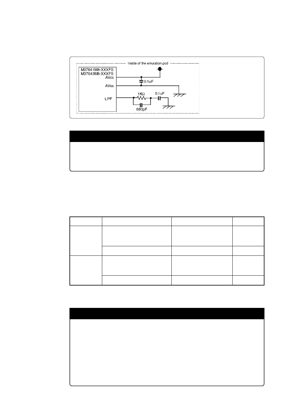
(3) Pins LPF, AVss and AVcc
These pins are processed in the emulation pod, and not connected to the target system. The connection
in the emulation pod is shown in Figure 3.9 below.
Figure 3.9 Connecting pins LPF, AVss and AVcc
IMPORTANT
Note on Connecting USB-related Pins:
• Pins LPF, AVss and AVcc are not connected to the target system.