Location and function of controls – Runco DTV-940/943 User Manual
Page 9
2-1
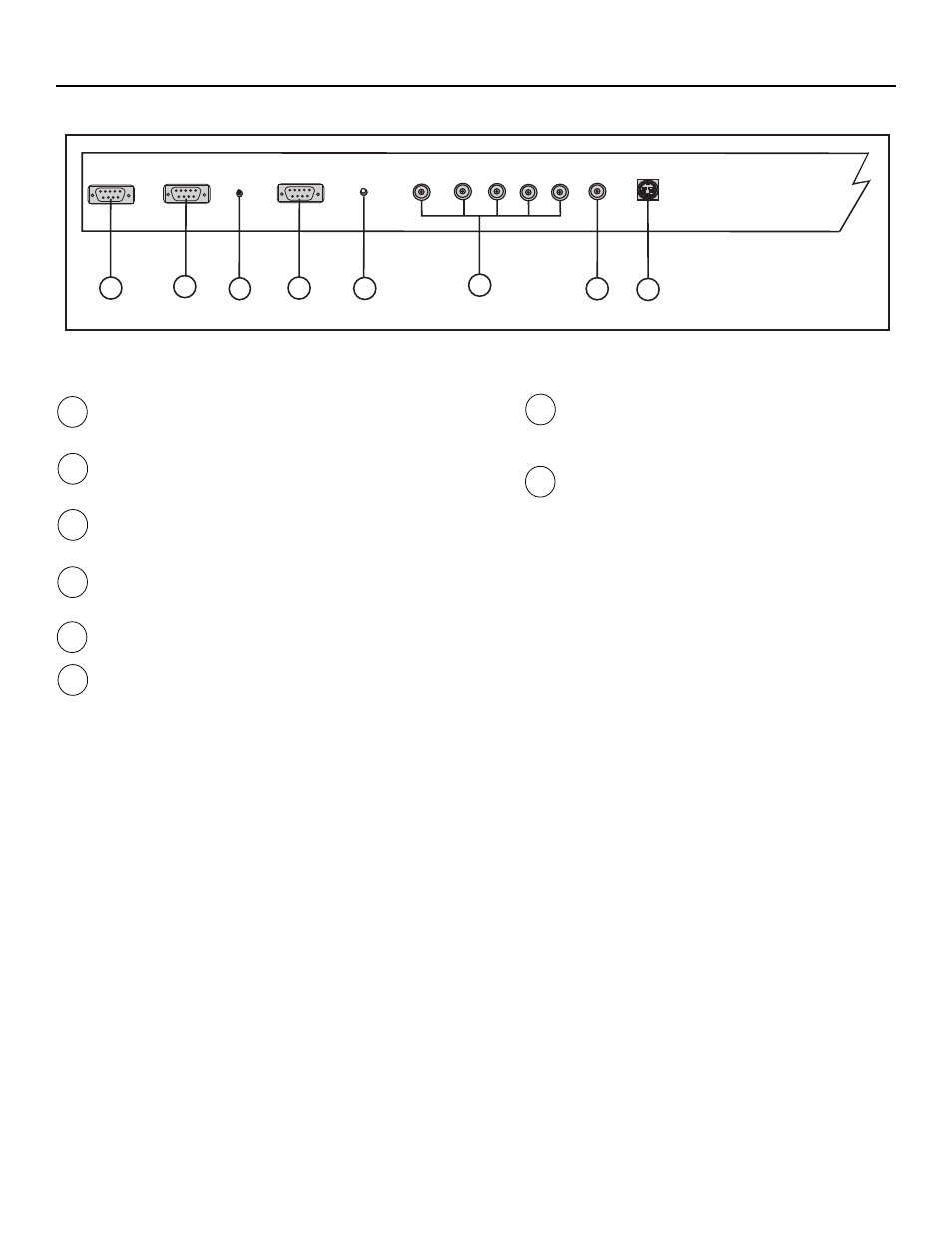
LOCATION AND FUNCTION OF CONTROLS
RS 232 Input Port
Connection between the controller and projector. Connect the RS-
232 output from the controller to this port.
RS 232 Output Port
RS 232 Input Port allows a communication link for PC or MAC to
the next projector in a series of projectors.
IR Sensor
Receiver for control signals transmitted from the RCU.
Communication Port -not used.
IR Remote
Connector for remote input for hard wired remote control
RGBHV or Component Input (5x BNC connector):
Connect the RGB output from the VHD controller here.
Line inputs:
-signals RED-GREEN-BLUE
-Horizontal and Vertical Sync
-If using Composite Sync, connect it to ‘H’.
(R-Y)Y(B-Y)-S Input (component input): allows to connect e.g. a
DTV Decoder having component outputs to the projector.
Line inputs
-signals RED-LUMA, LUMA, BLUE-LUMA
1
2
3
4
5
6
VIDEO Input (Composite video, 1x BNC connector):
Allows a video tape recorder, video camera, color receiv-
er/monitor, etc. having video line output to be connected
to the projector.
S-VIDEO Input: Separated Y/C (luma-chroma) signal
inputs and outputs for higher quality playback of DVD
signals (4-pin S-VIDEO connector loop-through).
7
8
RS232 IN
RS232 OUT
IR
COMM PORT
REMOTE
R
G(s)
B H V VIDEO S - VIDEO
This device complies with part 15 of
the FCC rules. Operation is subject to
following two conditions (1), This
device may not cause harmful inter-
ferance, and (2) this device must
accept any interferance received
including interferance that may cause
undesired operation.
1
2
3
4
5
6
7
8