Buffered two-signal edge-separation measurement – National Instruments NI USB-621x User Manual
Page 99
Chapter 9
Counters
© National Instruments Corporation
9-19
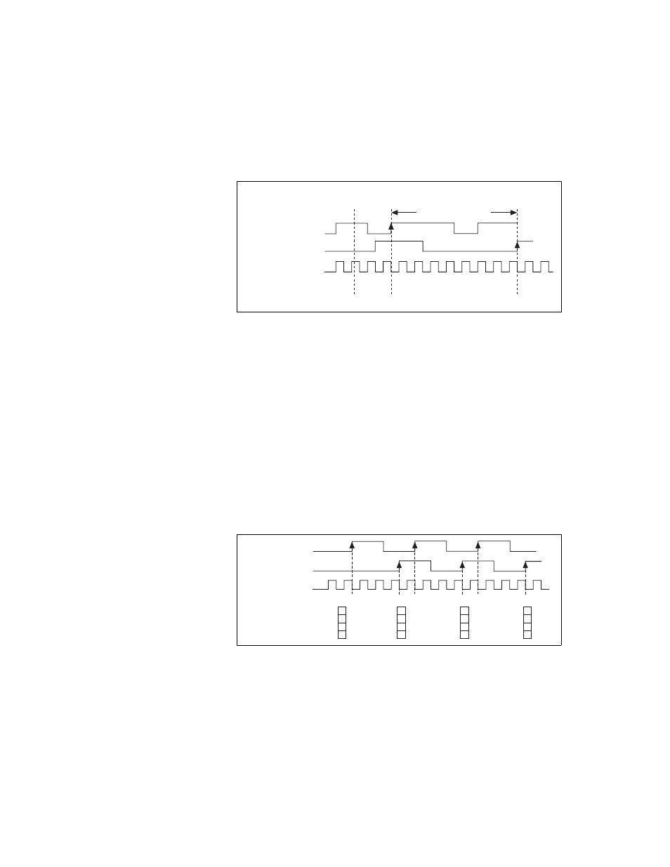
Figure 9-20 shows an example of a single two-signal edge-separation
measurement.
Figure 9-20. Single Two-Signal Edge-Separation Measurement
Buffered Two-Signal Edge-Separation Measurement
Buffered and single two-signal edge-separation measurements are similar,
but buffered measurement measures multiple intervals.
The counter counts the number of rising (or falling) edges on the Source
input occurring between an active edge of the Gate signal and an active
edge of the Aux signal. The counter then stores the count in a hardware save
register. On the next active edge of the Gate signal, the counter begins
another measurement. A USB Signal Stream transfers the stored values to
host memory.
Figure 9-21 shows an example of a buffered two-signal edge-separation
measurement.
Figure 9-21. Buffered Two-Signal Edge-Separation Measurement
For information about connecting counter signals, refer to the
section.
AUX
Counter
Armed
8
0
0
0
0
1
2
3
4
5
6
7
8
8
8
Measured Interval
GATE
SOURCE
Counter Value
HW Save Register
SOURCE
Counter Value
Buffer
AUX
GATE
1
2
3
1
2
3
1
2
3
3
3
3
3
3
3