Chapter 3 connector information, I/o connector signal descriptions, Table 3-1. i/o connector signals – National Instruments NI USB-621x User Manual
Page 24: I/o connector signal descriptions -1, Connector information
© National Instruments Corporation
3-1
3
Connector Information
The I/O Connector Signal Descriptions and
sections contain
information about NI 621x connectors. Refer to Appendix A,
, for device I/O connector pinouts.
I/O Connector Signal Descriptions
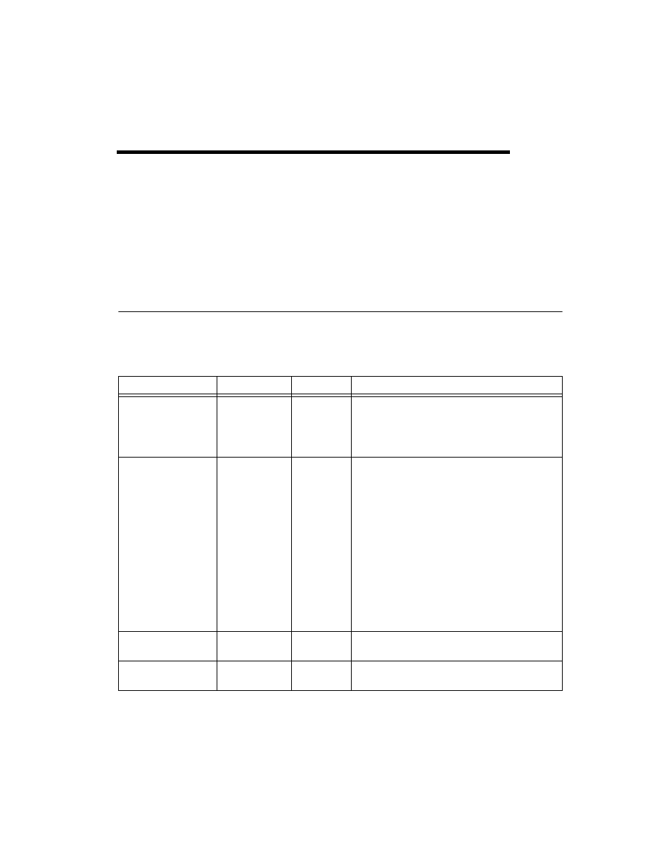
Table 3-1 describes the signals found on the I/O connectors. Not all signals
are available on all devices.
Table 3-1. I/O Connector Signals
Signal Name
Reference
Direction
Description
AI GND
—
—
Analog Input Ground—These terminals are the
reference point for single-ended AI measurements in
RSE mode and the bias current return point for DIFF
measurements. All three ground references—AI GND,
AO GND, and D GND—are connected on the device.
AI <0..31>
Varies
Input
Analog Input Channels 0 to 31—For single-ended
measurements, each signal is an analog input voltage
channel. In RSE mode, AI GND is the reference for these
signals. In NRSE mode, the reference for each
AI <0..31> signal is AI SENSE.
For differential measurements, AI 0 and AI 8 are the
positive and negative inputs of differential analog input
channel 0. Similarly, the following signal pairs also form
differential input channels:
AI SENSE
—
Input
Analog Input Sense—In NRSE mode, the reference for
each AI <0..31> signal is AI SENSE.
AO <0..1>
AO GND
Output
Analog Output Channels 0 to 1—These terminals
supply the voltage output of AO channels 0 to 1.