Figure 9-9. buffered period measurement, Table 9-1. time n descriptions – National Instruments NI USB-621x User Manual
Page 88
Chapter 9
Counters
9-8
ni.com
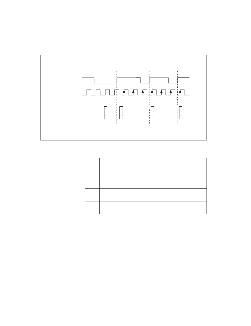
Figure 9-9. Buffered Period Measurement
Note that if you are using an external signal as the Source, at least one
Source pulse should occur between each active edge of the Gate signal.
This condition ensures that correct values are returned by the counter. If this
condition is not met, the counter returns a zero. Refer to the
section for more information.
For information about connecting counter signals, refer to the
section.
Table 9-1. Time N Descriptions
t
0
At t
0
, the counter is armed. No measurements are taken until
the counter is armed.
t
1
The rising edge of Gate indicates the beginning of the first
period to measure. The counter begins counting rising edges of
Source.
t
2
The rising edge of Gate indicates the end of the first period. The
USB M Series device stores the counter value in the buffer.
t
3
The rising edge of Gate indicates the end of the second period.
The USB M Series device stores the counter value in the buffer.
SOURCE
GATE
Counter Value
Buffer
1
3
3
3
1
1
2
2
3
3
3
Counter Armed
Time N
3
t
0
t
1
t
2
t
3