Retriggerable single pulse generation, Figure 9-24. retriggerable single pulse generation, Retriggerable single pulse generation -21 – National Instruments NI USB-621x User Manual
Page 101
Chapter 9
Counters
© National Instruments Corporation
9-21
Figure 9-23 shows a generation of a pulse with a pulse delay of four and a
pulse width of three (using the rising edge of Source).
Figure 9-23. Single Pulse Generation with Start Trigger
Retriggerable Single Pulse Generation
The counter can output a single pulse in response to each pulse on a
hardware Start Trigger signal. The pulses appear on the Counter n Internal
Output signal of the counter.
You can route the Start Trigger signal to the Gate input of the counter. You
can specify a delay from the Start Trigger to the beginning of each pulse.
You also can specify the pulse width. The delay and pulse width are
measured in terms of a number of active edges of the Source input.
The counter ignores the Gate input while a pulse generation is in progress.
After the pulse generation is finished, the counter waits for another Start
Trigger signal to begin another pulse generation.
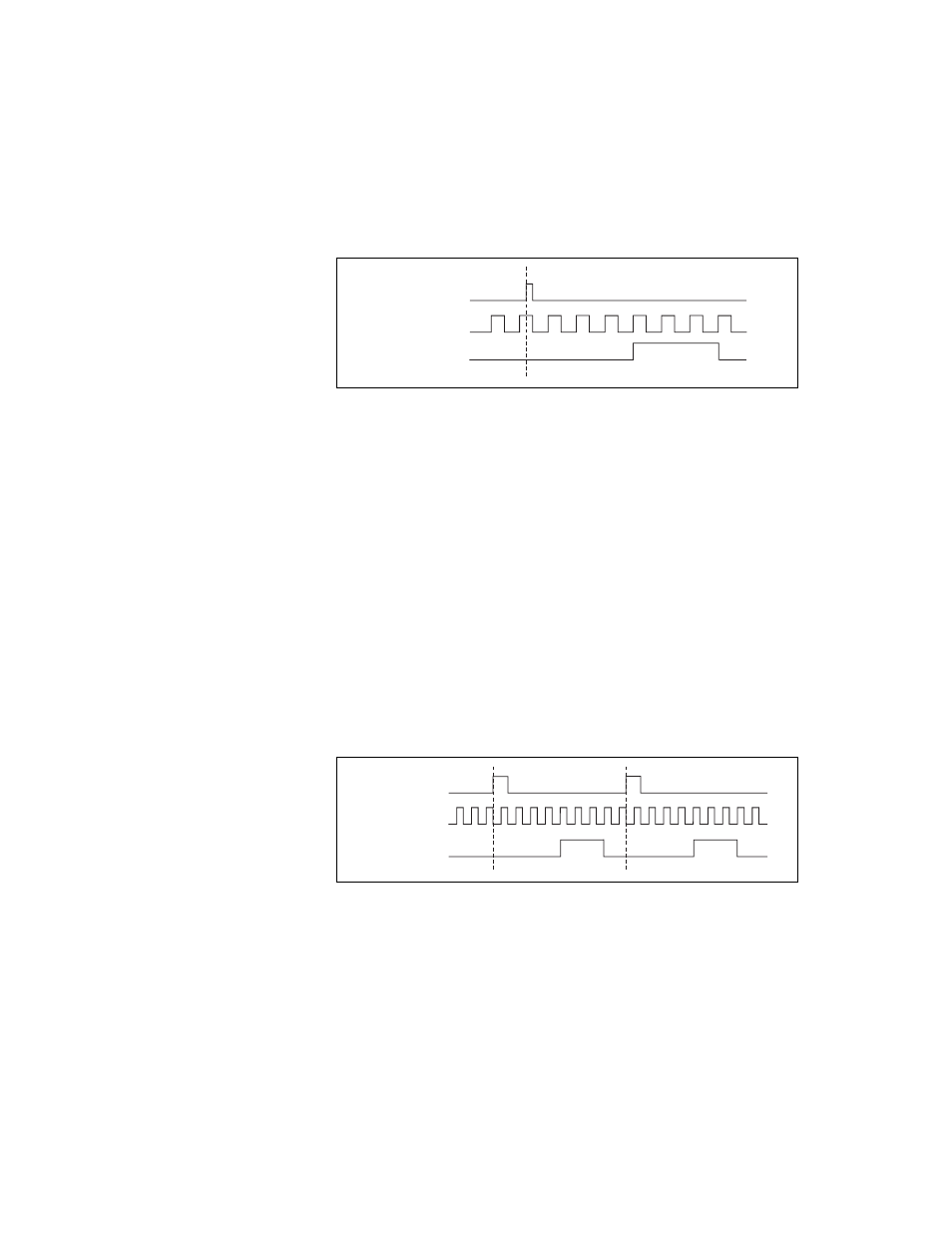
Figure 9-24 shows a generation of two pulses with a pulse delay of five and
a pulse width of three (using the rising edge of Source).
Figure 9-24. Retriggerable Single Pulse Generation
For information about connecting counter signals, refer to the
section.
SOURCE
GATE
(Start Trigger)
OUT
SOURCE
GATE
(Start Trigger)
OUT