Figure 2-2. usb-621x block diagram, Daq-stc2, Calibration circuitry – National Instruments NI USB-621x User Manual
Page 21: Daq-stc2 -2 calibration circuitry -2
Chapter 2
DAQ System Overview
2-2
ni.com
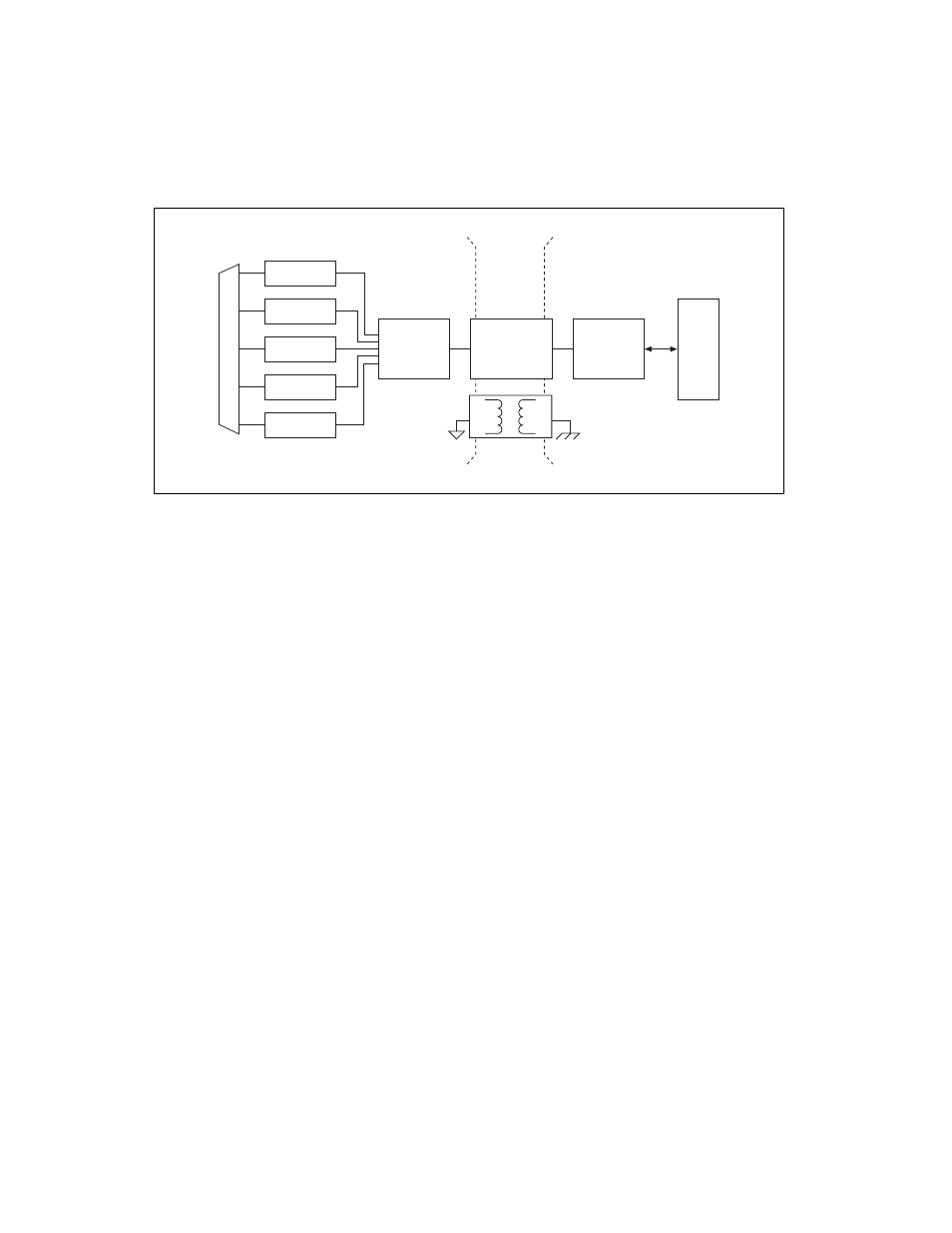
Figure 2-2. USB-621x Block Diagram
DAQ-STC2
The DAQ-STC2 implements a high-performance digital engine for
M Series data acquisition hardware. Some key features of this engine
include the following:
•
Flexible AI and AO sample and convert timing
•
Many triggering modes
•
Independent AI, AO, and CTR FIFOs
•
Generation and routing of internal and external timing signals
•
Two flexible 32-bit counter/timer modules with hardware gating
•
Static DI and static DO signals
•
USB Hi-Speed 2.0 interface
•
Up to four USB Signal Streams for acquisition and generation
functions
Calibration Circuitry
The M Series analog inputs and outputs have calibration circuitry to correct
gain and offset errors. You can calibrate the device to minimize AI and AO
errors caused by time and temperature drift at run time. No external
circuitry is necessary; an internal reference ensures high accuracy and
stability over time and temperature changes.
Analog Output
Digital I/O
Analog Input
Counters
PFI
Digital
Routing
and Clock
Generation
Bus
Interface
Bus
I/O Connector
Digital
Isolators
Isolation
Barrier
(USB-6215
and USB-6218
devices only)