Chapter 11 isolation and digital isolators, Table 11-1. ground symbols, Figure 11-1. general ni 621x block diagram – National Instruments NI USB-621x User Manual
Page 125: Isolation and digital isolators
© National Instruments Corporation
11-1
11
Isolation and Digital Isolators
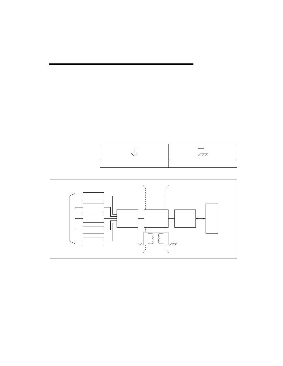
USB-6215/6218 devices are isolated data acquisition devices. As shown in
Figure 11-1, the analog input, analog output, counters, PFI/static DI, and
PFI/static DO circuitry, and digital routing and clock generation are
referenced to an isolated ground. The bus interface circuitry is referenced
to a non-isolated ground. Refer to Table 11-1 for an example of the
symbols for isolated ground and non-isolated ground.
Figure 11-1. General NI 621x Block Diagram
The non-isolated ground is connected to the chassis ground of the PC.
Each isolated ground is not connected to the chassis ground of the PC. The
isolated ground can be at a higher or lower voltage relative to the
non-isolated ground. All analog measurements are made relative to the
isolated ground signal.
Table 11-1. Ground Symbols
Isolated Ground
Non-Isolated Ground
Analog Output
Digital I/O
Analog Input
Counters
PFI
Digital
Routing
and Clock
Generation
Bus
Interface
Bus
I/O Connector
Digital
Isolators
Isolation
Barrier
(USB-6215
and USB-6218
devices only)