Installing the m-ata, Smartlink m-ata installation diagram – Patton electronic Patton SmartLink M-ATA User Manual
Page 20
Installing the M-ATA
20
SmartLink M-ATA Getting Started Guide
2 • SmartLink installation
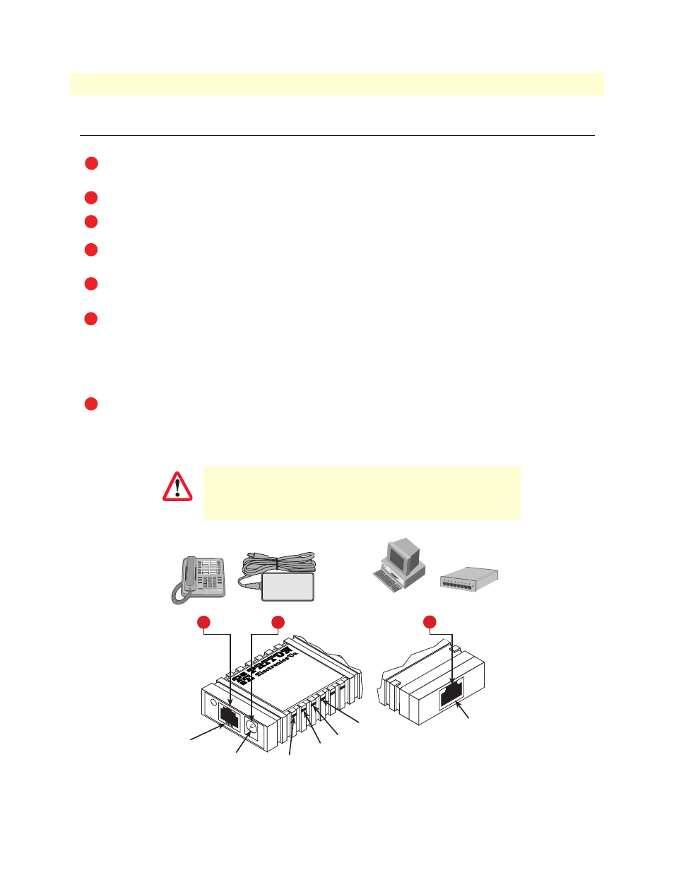
Installing the M-ATA
Note
The default password for the M-ATA is “
root”
.
Figure 2.
SmartLink M-ATA
installation diagram
The unit should be installed in a dry environment with at least 2 inches (5 cm) of clearance at the sides,
front, and rear of the unit to allow air circulation for cooling.
).
Plug in the PC or LAN, or a LAN hub/switch.
Plug the power adapter into the power jack on the SmartLink M-ATA (see
end of the power cord to an appropriate AC power outlet.
Wait 30 seconds after powering the SmartLink M-ATA on, then verify that the green
Power
LED is lit
(see
By default, the M-ATA will automatically request IP network settings from the LAN using DHCP. To
determine the IP address of the SmartLink, lift the handset off the attached analog phone and dial
* * * *
.
Dial
1 0 0 #
, listen to and record the IP address of the SmartLink. (To manually set the IP address, see
Use a web browser to connect to the SmartLink M-ATA. The URL will be http://
example, if the M-ATA IP address was
10.10.10.2
, the URL would be
http://10.10.10.2
.
Follow the directions of your voice service provider to set up
voice services.
1
2
3
4
5
6
7
IMPORTANT
Phone LED
Power LED
System LED
LAN LED
Gaithersburg, Maryland
M-
ATA
Micro-Analog
Telephone Adapter
PHONE
LAN
SYSTEM
POWER
Power jack
Power adapter
LAN port
3
PC or
LAN
--or--
LAN
Hub/Switch
Phone
Phone jack
2
4
Front
view
Rear
view