0 operation, 1 led descriptions, Operation – Patton electronic 2710 User Manual
Page 33: Led descriptions
33
5.0 OPERATION
Once the NetLink-T1™ is installed and conÞgured properly it is ready to
place into operation. This section describes the function of the LED indi-
cators, and the use of the loopback and pattern test modes.
5.1 LED DESCRIPTIONS
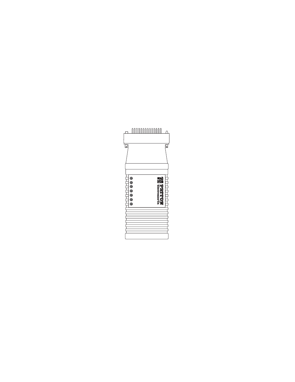
The NetLink-T1™ is equipped with seven LED indicators that monitor the
status of communication. Figure 4 (below) shows the location of the
LEDs on the NetLink-T1™ Series front panel.
Figure 4. Top of NetLink-T1™, Showing LED Indicators
TXD– When the unit sends a one, the TXD LED is turned on. When
it sends a zero, the TXD LED is turned off. Moreover, the TXD LED
is active only in active DS0 channels. In inactive channels, the TXD
LED is off.
RXD– When the unit receives a one, the RXD LED is turned on.
When it receives a zero, the RXD LED is turned off. Moreover, the
RXD LED is active only in active DS0 channels. In inactive channels,
the RXD LED is off.
RXD
LOS
ALM
ERR
T/L
PWR
TXD
Model 2711