0 installation, 1 dte interface connection, 2 network interface connection – Patton electronic 2710 User Manual
Page 31: Installation, Dte interface connection, Network interface connection
31
4.0 INSTALLATION
The NetLink-T1™ is equipped with DTE, network, and power interfaces.
This section brießy describes connection to each.
4.1 DTE INTERFACE CONNECTION
The DTE interface is a V.35 DCE presented as an M/34 male connector.
This interface is designed to plug directly into a DTE interface (See
Appendix D on page 41 for V.35 interface pin assignments).
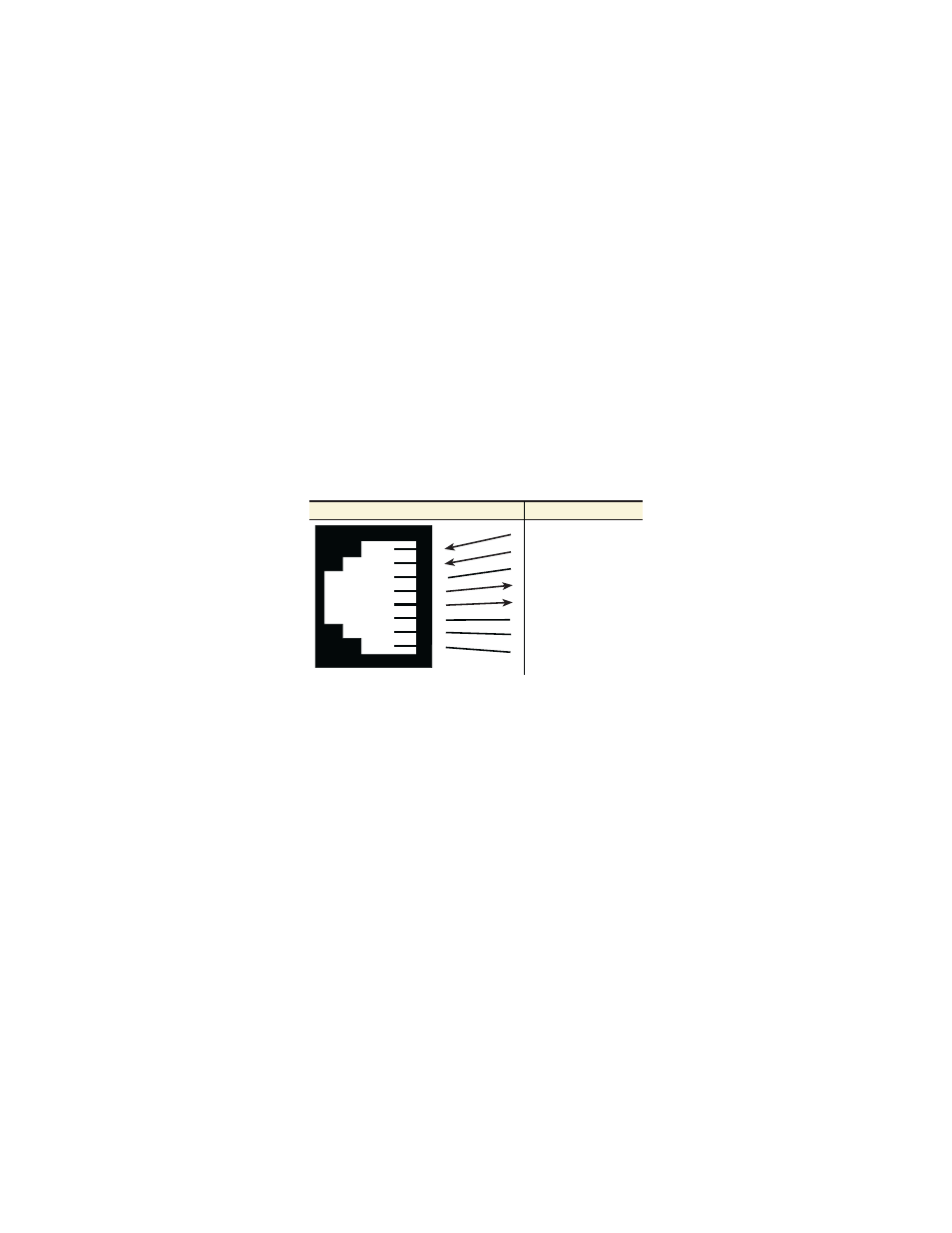
4.2 NETWORK INTERFACE CONNECTION
The Network Line Interface is an eight position keyed modular jack con-
Þgured as a RJ-48C. This interface will need to be conÞgured to match
the line parameters (i.e. framing, line coding, etc.) supplied by the cen-
tral ofÞce.
Figure 3. NetLink-T1™ twisted pair line interface.
Note
If the NetLink-T1™ is being used for private short range modem
applications, the twisted pair cable connected to its port will
need to be a cross-over cable. See Appendix D on page 41 for
Interface pin assignments.
1
2
3
4
5
6
7
8
1
2
3
4
5
6
7
8
(RX) Receive (Ring)
(RX) Receive (Tip)
Shield
(TX) Transmit (Ring)
(TX) Transmit (Tip)
Shield
No connection
No connection
Signal Name
RJ-48C Jack