0 configuration, 1 dip switch configuration, Configuration – Patton electronic 2710 User Manual
Page 10: Dip switch configuration
10
3.0 CONFIGURATION
The Model 2710 features conÞguration capability via hardware switches
or a software control port. This section describes all possible hardware
and software switch conÞgurations of the NetLink-T1™.
3.1 DIP SWITCH CONFIGURATION
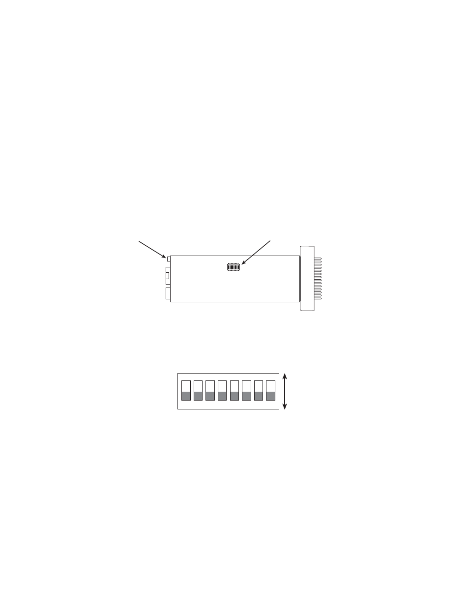
The Model 2710 has eight internal DIP switches that allow conÞguration
for a wide range of applications. The eight switches are accessed by
opening the plastic case with a small screwdriver. Figure 1 (below)
shows the location of the DIP switches on the bottom of the printed cir-
cuit board.
Figure 1.
Model 2710 Series bottom view, showing location of DIP switches
The Model 2710 DIP switches (Switches SW1 - SW8) can be conÞgured
as either “On” or “Off”. Figure 2 (below) shows the orientation of the DIP
switches with respect to ON/OFF positions.
Figure 2.
Close up of DIP switches showing ON/OFF positions.
ON
1 2 3 4 5 6 7 8
Software Configuration Port
ON
OFF
DIP Switches
1
2
3
4
5
6
7
8
ON
ON
OFF