E input capacitor discharge procedure, Steps 3 thru 7, Troubleshooting & repair – Lincoln Electric V155-S User Manual
Page 42: Warning
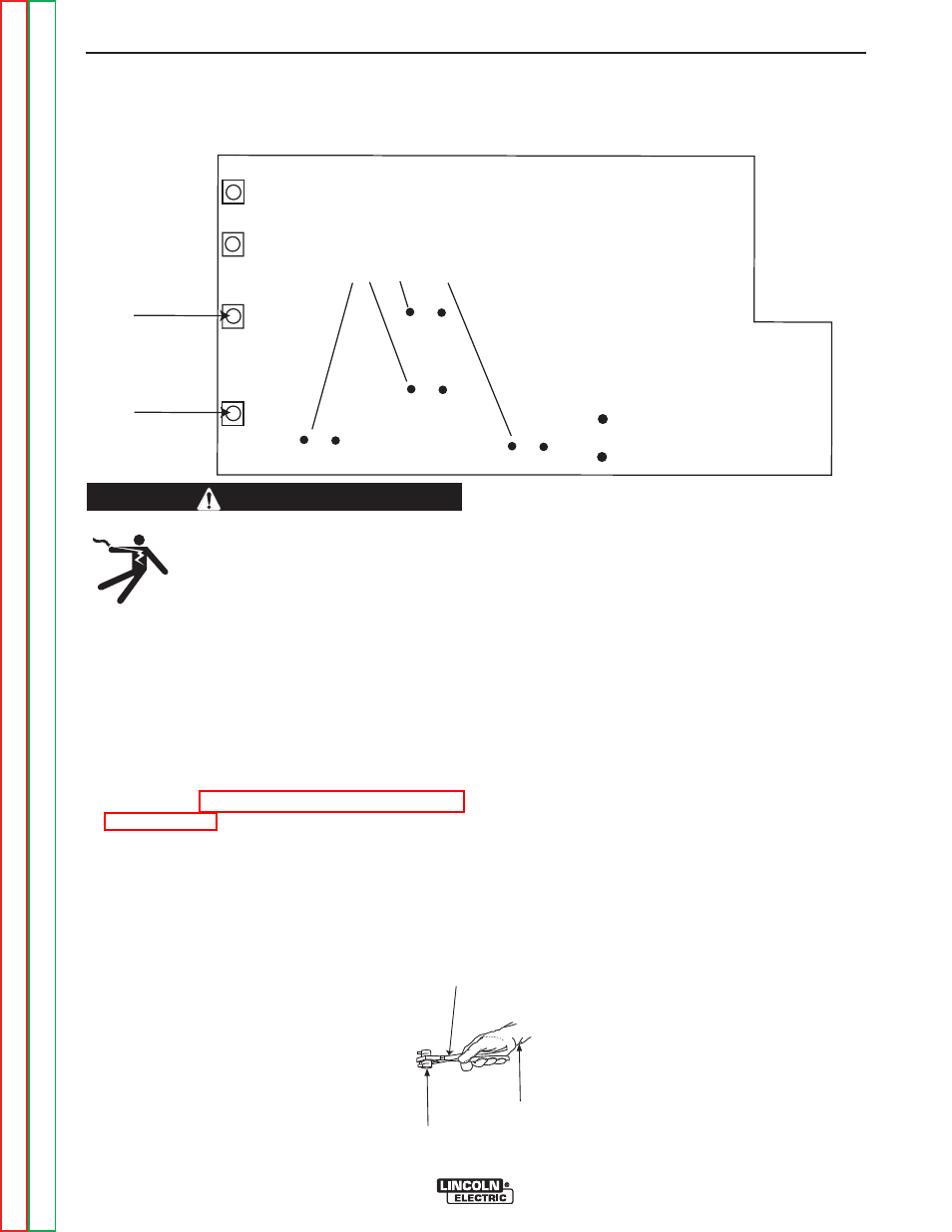
DC+
DC-
INPUT BOARD
CAPACITOR TERMINALS
(4 places)
FIGURE F.2 – CAPACITOR DISCHARGE LOCATIONS
FIGURE F.3 – GLOVE, PLIERS & REISISTOR
INPUT FILTER CAPACITOR DISCHARGE PROCEDURE (CONTINUED)
TROUBLESHOOTING & REPAIR
F-10
F-10
INVERTEC® V155-S
ELECTRIC SHOCK
can kill.
• Have an electrician install and service
this equipment.
• Turn the input power off at the fuse box
before working on equipment.
• Do not touch electrically hot parts.
• Prior to performing preventative maintenance,
perform the following capacitor discharge procedure
to avoid electric shock.
PROCEDURE
1. Disconnect power to the INVERTEC® V155-S.
2. Perform the Case Cover Removal Procedure,
3. Locate the Input Board.
4. Obtain a high resistance and high wattage resistor
(25-1000 ohms and 25 watts minimum). This resis-
tor is NOT supplied with the machine. NEVER USE
A SHORTING STRAP FOR THIS PROCEDURE.
5. Locate the two terminals DC+ and DC- on the Input
Board. See Figure F.2.
6. Use electrically insulated gloves and insulated pli-
ers. Hold the body of the resistor and connect the
resistor leads across the two terminals. Hold the
resistor in place for 10 seconds. DO NOT TOUCH
CAPACITOR TERMINALS WITH YOUR BARE
HANDS. See Figure F.3.
7. Check the voltage across the terminals of all
capacitors with a DC voltmeter. Voltage should be
zero. If any voltage remains, repeat this capacitor
discharge procedure.
WARNING
INSULATED
PLIERS
INSULATED
GLOVES
RESISTOR