Figure f.34, See figure f.34, Troubleshooting and repair – Lincoln Electric VRTEXTM 360 SVM200-A User Manual
Page 134
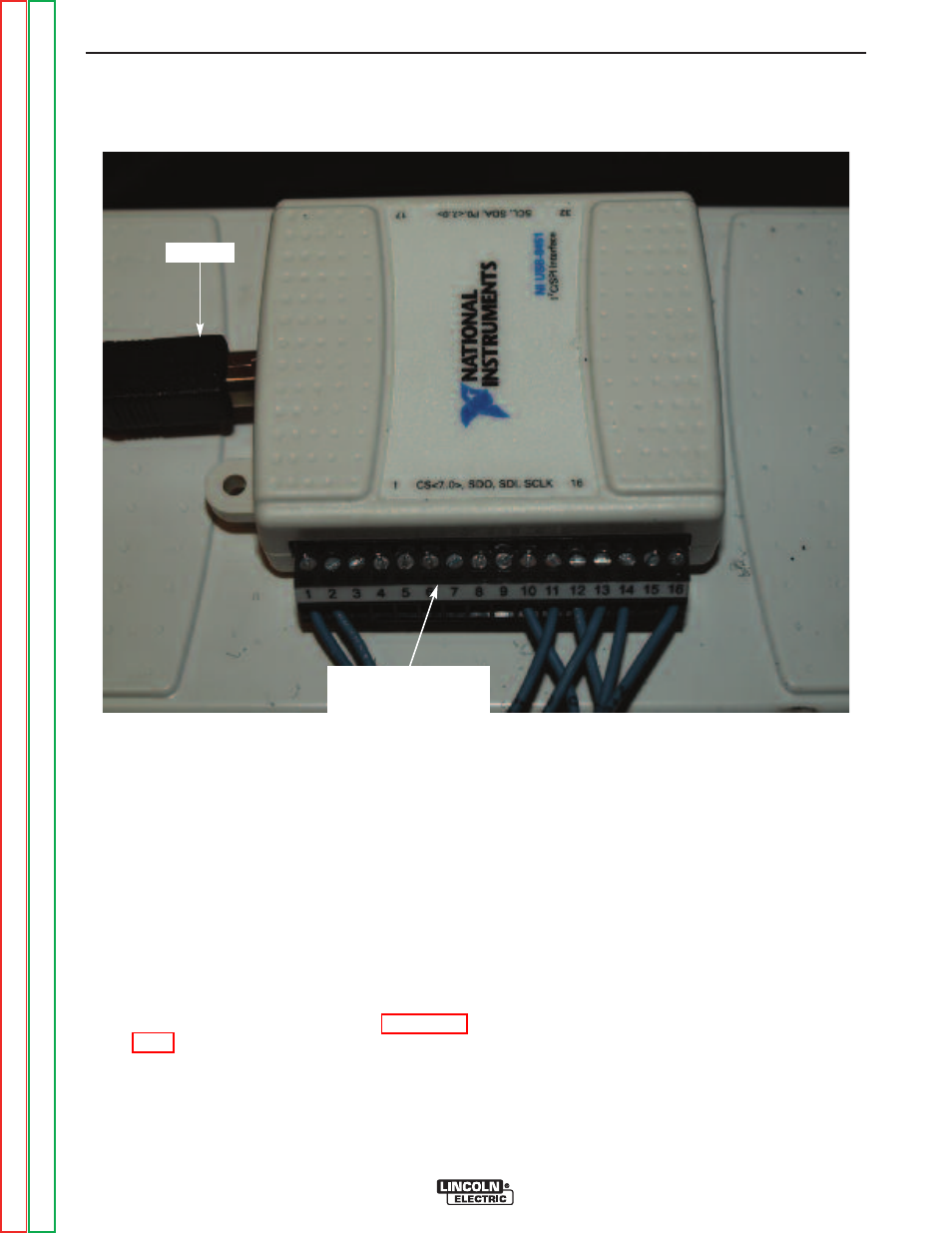
FIGURE F.34 – PLUG & TERMINAL STRIP LOCATION
INTERFACE MODULE (USB)
REMOVAL AND REPLACEMENT PROCEDURE (continued)
REPLACEMENT PROCEDURE
1. Install the new Interface Module (USB) using
Hook & Loop mounting pads.
2. Install the 16-pin terminal strip previously
removed.
NOTE:
The terminal strip must be plugged into the
side marked 1 thru 16 (NOT 17 thru 32) on
the Interface Module (USB).
3. Connect the previously removed USB cable.
4. Connect USB mouse and USB keyboard to an
available/open USB port on CPU.
5. Turn on the input power to the machine.
6. Wait for “Shortcut to Start-up Sim”. See Figure
7. Press “x” to cancel loading. At this point, a
basic computer screen desktop will appear.
8. Computer may show a “found new hardware”
screen. Click “next”. Then click on “connect to
internet”.
NOTE:
Internet connection is not necessary.
9. Click on “Install the software automatically” and
then click “next”.
10. After the driver is installed successfully, click
“finished”.
TROUBLESHOOTING AND REPAIR
F-77
F-77
VRTEX
TM
360
16-PIN
TERMINAL STRIP