See figure, F.30, Figure f.30 – Lincoln Electric VRTEXTM 360 SVM200-A User Manual
Page 130: See figure f.30, Troubleshooting and repair
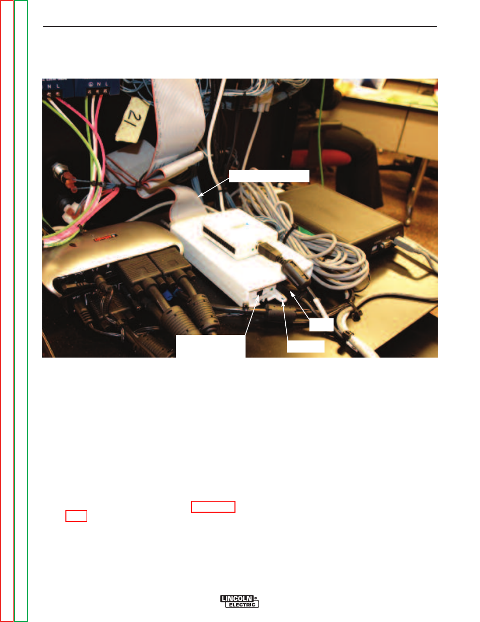
FIGURE F.30 – PLUG LOCATIONS
INTERFACE MODULE DIGITAL I/O
REMOVAL AND REPLACEMENT PROCEDURE (continued)
REPLACEMENT PROCEDURE
1. Install the new Interface Module Digital I/O and
secure using the previously removed screw.
2. Connect the previously removed USB cable.
3. Connect the large ribbon cable previously
removed.
NOTE:
Make sure that the slide switch at the rear
of the Module is in the “HIGH” position.
4. Connect USB mouse and USB keyboard to an
available/open USB port on CPU.
5. Turn on the input power to the machine.
6. Wait for “Shortcut to Start-up Sim”. See Figure
7. Click “x” to close screen and cancel loading. At
this point, a basic computer screen desktop will
appear.
8. Computer may show a “found new hardware”
screen. Click “next”. Then click on “connect to
internet”.
NOTE:
Internet connection is not necessary.
9. Click on “Install the software automatically” and
then click “next”.
10. After the driver is installed successfully, click
“finished”.
TROUBLESHOOTING AND REPAIR
F-73
F-73
VRTEX
TM
360
SLIDE SWITCH
(Set to HIGH)
USB
RIBBON CABLE
SCREW