Aprs- packet monitor display, Dx packetclusters monitor – Kenwood RC-D710 User Manual
Page 56
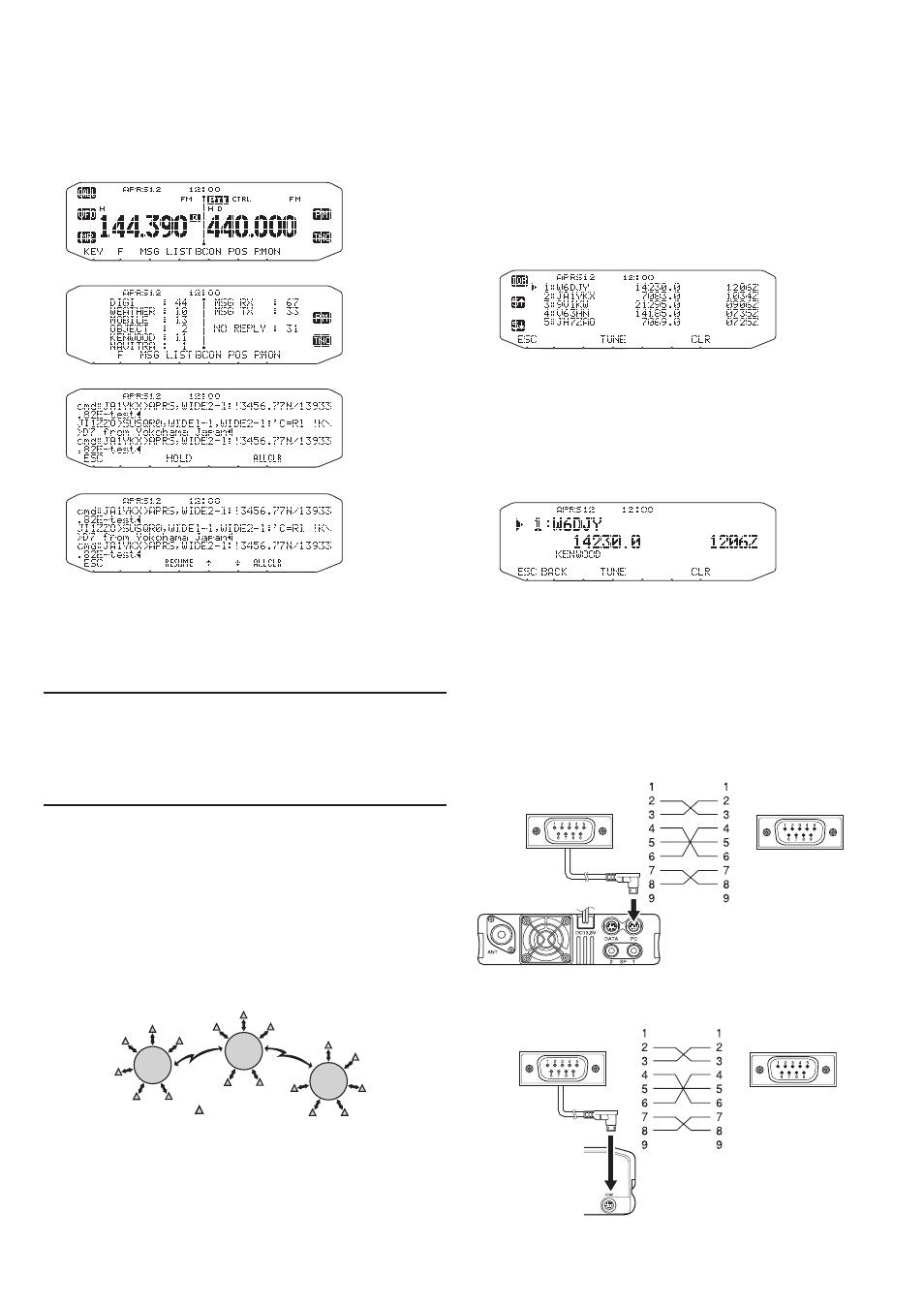
APRS-
PACKet monitoR DiSPlAy
This transceiver presents Terminal Window mode to
display raw data of received APRS packets. It displays up
to 155 characters per page and holds up to 10 pages.
1 Press [KEY], [P.MON] (or [P.MON]) .
• To enter Terminal Window mode.
2 To access old pages, press [HOLD].
• Rotate the
Tuning control or press [
↑] or [↓] to change
the page.
• Press
[RESUME] to quit the Hold function.
• While using the Hold function, newly received packets will
not be stored in buffer.
• When press
[ALLCLR], packet monitor display is cleared.
Note:
u
The terminal window is not available for sending a command to
the TNC.
u
The terminal window is available in APRS mode (not in Packet
mode).
u
The data in buffer is cleared when the transceiver power is turned
OFF.
Dx PACKetCluSteRS monitoR
DX PacketClusters are networks which consist of nodes
and stations who are interested in DXing and contesting. If
one station finds a DX station on the air, he (or she) sends
a notice to his (or her) node. Then this node passes the
information to all its local stations besides another node. This
transceiver can display received DX information and hold the
latest information on up to 10 DX stations. Use this function
to monitor the latest DX information in your local area. You
cannot send DX information to a node, using the function.
1 Access Menu 601 (INTERNAL TNC - DATA BAND) to
select band A or B
• If the common transfer rate in your local PacketCluster
network is 9600 bps, access Menu 601 (INTERNAL TNC
- PACKET SPEED) and select “9600 bps”.
2 Tune to the frequency of the target PacketCluster
node.
3 Press [TNC] to enter APRS mode.
• “APRS” should appear.
4 Press [F], [DX].
• Each time new DX cluster data is received, a call sign,
frequency, and time are displayed.
• Information of up to 5 DX stations are displayed at the
same time.
• When a duplicate DX cluster data is received, “dD” and a
call sign are displayed.
[TOP]: Displays the list of the fast 5 stations.
[5
↑]: Displays the list of the previous 5 stations.
[5
↓]: Displays the list of the next 5 stations.
[ESC]: Restores the frequency display..
[TUNE]: Outputs the PCT data.
[CLR]: Deletes the current DX station.
• DX station detailed display mode
[ESC]: Restores the frequency display.
[BACK]: Returns to the DX station list
[TUNE]: Outputs the PCT data.
[CLR]: Deletes the current DX station.
n
Connecting with the HF transceiver
You may use a commercially available RS-232-C
cross-wired cable.
• A D-SUB female/male conversion adapter is required.
PG-5G
HF transceiver
TM-V71
COM connector on HF
transceiver
(f)
(m)
PG-5G
HF transceiver
RC-D710
COM connector on HF
transceiver
(f)
(m)
Node
Node
Node
Station