Aprs- selecting a navitra group, Storing navitra message, Setting smartbeaconing – Kenwood RC-D710 User Manual
Page 55
APRS-
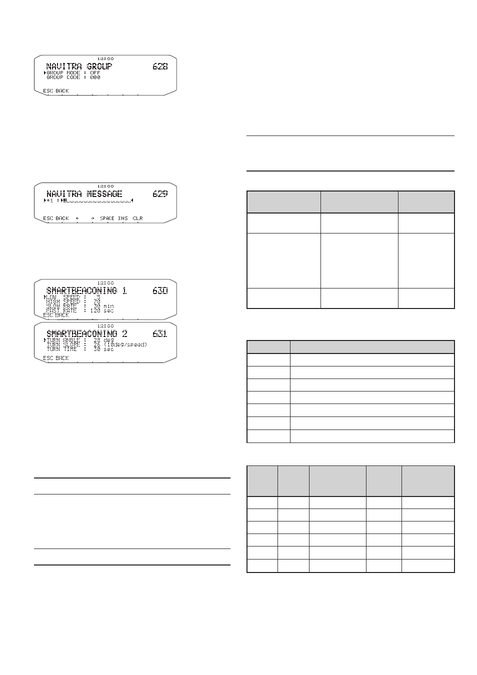
SeleCting A nAVitRA gRouP
Enter Menu mode and access Menu 628.
n
group mode
Select to Group mode ON or OFF.
n
enter group Code
You can enter 0 to 9, A to Z.
StoRing nAVitRA meSSAge
Enter Menu mode and access Menu 629.
You can create up to 5 phrases each of which can consist
of up to 20 characters.
Setting SmartBeaconing
tm
Enter Menu mode and access Menu 630 and 631.
Set to use [SmartBeaconing] (Menu No.611) with APRS
data transmission.
This function optimizes beacon transmission based on
driving direction and speed. Use this function when you
want to track your transmissions, especially for optimizing
crossover beacon transmission intervals.
n
low speed
Low speed setting (2 ~ 30
When the speed is lower than this, beacons are
transmitted at the time interval specified under SLOW
RATE.
Note: To select the speed setting of the units, access Menu 626
(DISPLAY UNIT 1 - SPEED, DISTANCE).
n
High speed
High speed setting (2 ~70
When the speed is faster than this, beacons are
transmitted at the time interval specified under FAST
RATE.)
Note: To select the speed setting of the units, access Menu 626
(DISPLAY UNIT 1 - SPEED, DISTANCE).
n
Slow rate
Low speed transmission interval time
(1 ~ 100 minutes).
n
Fast rate
High speed transmission interval time
(10 ~ 180 seconds).
n
turn angle
Driving direction change, minimum value setting
(5 ~ 90 degrees).
n
turn slope
Driving direction change, additional value setting
(1 ~ 255 (10degrees/speed)).
n
turn time
Minimum time delay between each beacon
transmission (5 ~ 180 seconds).
Note:
u
When Menu No. 602 is set to a value other than [GPS], it
operates at the SLOW RATE.
u
Adjust the Setting values to match the actual driving status.
SmartBeaconing Operation:
Speed
Transmission
Interval
Corner
Pegging
Above the HIGH
SPEED
FAST RATE
Operates
normally
Under HIGH SPEED
Over LOW SPEED
(Only when the set
HIGH SPEED
≧
LOW SPEED)
The interval is
calculated using the
following formula:
(Transmission Interval
= FAST RATE x HI
SPEED ÷ Speed)
Operates
normally
Below the LOW
SPEED
SLOW RATE
Will not
operate
Transmission Interval Example:
(with LOW SPEED = 5, HIGH SPEED = 70, SLOW RATE
= 30 min, FAST RATE = 120 sec)
Speed
Interval
70
120 seconds (2 minutes)
50
168 seconds (2 minutes 48 seconds)
30
280 seconds (4 minutes 40 seconds)
20
420 seconds (7 minutes)
10
840 seconds (14 minutes)
5
1680 seconds (28 minutes)
0
1800 seconds (30 minutes)
Corner Pegging Operation Example:
(with TURN ANGLE = 28, TURN SLOPE = 26)
Speed TURN
SLOPE
TURN
SLOPE
÷
Speed (1)
TURN
ANGLE
(2)
Turn
Threshold
(3)=(1)+(2)
70
26
(x10)
3°
28
31°
50
26
(x10)
5°
28
33°
30
26
(x10)
8°
28
36°
20
26
(x10)
13°
28
41°
10
26
(x10)
26°
28
54°
5
26
(x10)
52°
28
80°
• When the value of [Turn Threshold] exceeds 120º, it is
calculated as 120º.
< SmartBeaconing™ from HamHUD Nichetronix >