Sanyo C4272R S/C User Manual
Page 96
SC
96
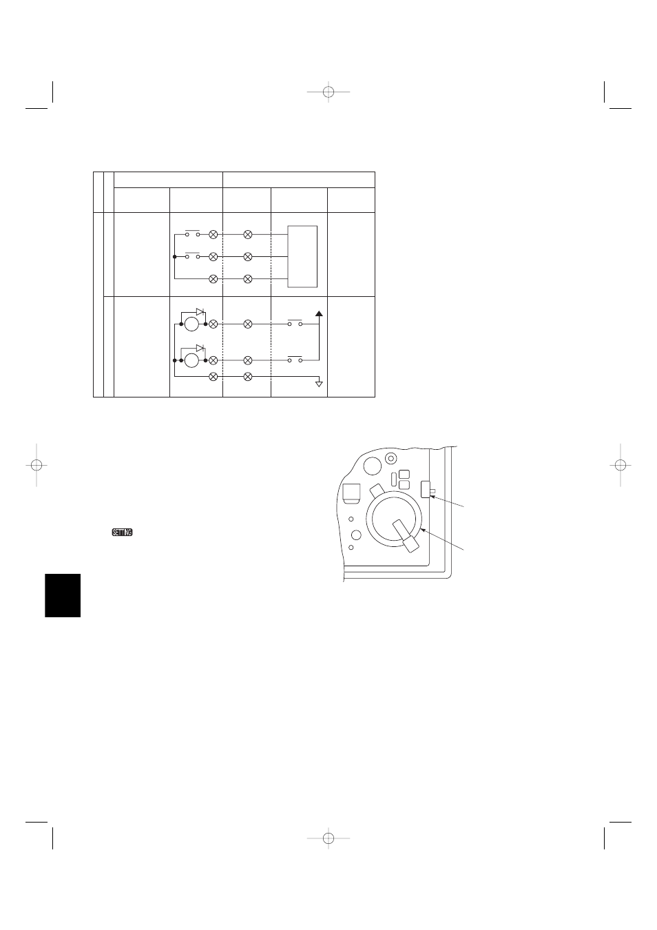
8-6. Connection with Other Equipment
ON/OFF
t
u
p
ni
l
ati
gi
D
Alarm
Output common
CPEV
AWG#16
ALL ON (+)
CX
TX
ALL OFF (+)
Input common
COM
+24
CPEV
AWG#16
e
m
a
N
sl
a
ni
mr
et
t
u
pt
u
o/t
u
p
ni
l
ati
gi
D
met
i t
upt
uo/
tu
pnI
t
u
pt
u
o
s
ut
at
S
t
u
p
ni
l
ort
n
o
C
ON/OFF output
Alarm output
Potential tree
A contact, static
(relay output)
Wire length:
less than 330 ft.
Input/output
System controller
Equipment
Input/output
Terminal
Terminal
Example
All ON input
All OFF input
Pulse (photo
coupler input)
Contact capacity
DC 24V, 10mA
Pulse width:
more than
984 ft./sec.
Wire length:
less than 330 ft.
Contact capacity
DC 30V, 0.5A
8-7. Memory Backup Switch
Check the backup switch is ON on the for back side of
the PCB of the system controller.
Back up switch
F
F
O
N
O
Back up battery
8-8. Test Run
(1)
Power on all indoor units. Next, power on the
system controller.
will flash, checking the indoor unit addresses
automatically.
(2)
If group No. displayed on system controller is not the
same as the indoor unit No.* which is connected, see
Fig. 9-5 and carry out setting again.
*In case of group control, main unit No. only.
07-115 SSHP_II 5/7/07 4:00 PM Page 96