How to install the indoor unit – Sanyo C4272R S/C User Manual
Page 26
X
26
3. HOW TO INSTALL THE INDOOR UNIT
■ 4-Way Air Discharge Semi-Concealed Type
(X Type)
3-1. Suspending the Indoor Unit
This unit uses a drain pump. Use a carpenter’s level to
check that the unit is level.
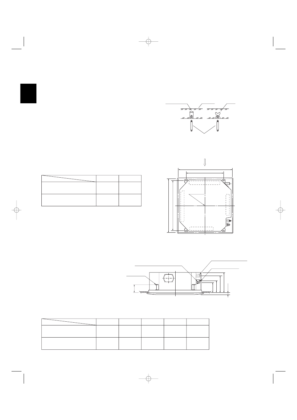
3-2. Preparation for Suspending
(1) Fix the suspension bolts securely in the ceiling
using the method shown in the diagrams (Figs. 3-1
and 3-2), by attaching them to the ceiling support
structure, or by any other method that ensures that
the unit will be securely and safely suspended.
(2) Follow Fig. 3-2 and Table 3-1 to make the holes in
the ceiling.
(3) Determine the pitch of the suspension bolts using
the supplied full-scale installation diagram. The
diagram and table (Fig. 3-3 and Table 3-2) show
the relationship between the positions of the sus-
pension fitting, the unit, and the panel.
Type
Length
Table 3-2
Unit: inch (mm)
XH(W)2672R
(PNR-XH2442)
XH(W)3672R, XH(W)4272R
(PNR-XH3632)
A
6-3/16
(157)
6-3/16
(157)
7-5/32
(182)
7-5/32
(182)
10-9/32
(261)
11-15/32
(291)
12-1/8
(308)
13-1/16
(338)
4-7/8
(124)
4-7/8
(124)
D
E
B
C
Hole-in-anchor
Hole-in-plug
Concrete
Insert
Suspension bolt (M10 or 3/8")
(field supply)
Fig. 3-1
)
g
ni
n
e
p
o
g
nili
e
C(
2
3/
9-
2
3
Grille center
ns
io
n
bolt pitch)
e
p
s
u
S(
6
1/
3
1-
9
2
X
Refrigerant
tubing side
Drain hose
side
B
(Suspension bolt pitch)
A (Ceiling opening)
Fig. 3-2
C
D
6
1/
3-
1
B
A
E
Suspension lug
Refrigerant tubing joint (gas tube side)
Refrigerant tubing joint
(liquid tube side)
Drain connection (other side)
(VP25)
Length
Type
Table 3-1
Unit: inch (mm)
XH(W)2672R
(PNR-XH2442)
XH(W)3672R, XH(W)4272R
(PNR-XH3642)
A
32-9/32
(820)
43-11/16
(1,110)
22-9/32
(566)
33-11/16
(856)
B
Unit: inch
Fig. 3-3
Unit: inch
07-115 SSHP_II 5/7/07 3:59 PM Page 26