Cabling the server – Sun Microsystems X4150 User Manual
Page 39
Chapter 3
Setting Up the Sun Fire X4150 Server
29
Cabling the Server
Connect the server power cables, and external cables in the following order:
1. Connect two grounded server power cords to grounded electrical outlets (1, 2).
Note –
Connect only one cable if your server does not have a redundant power
supply.
2. Connect the two server power cords to the AC power connectors on the back
panel of the server.
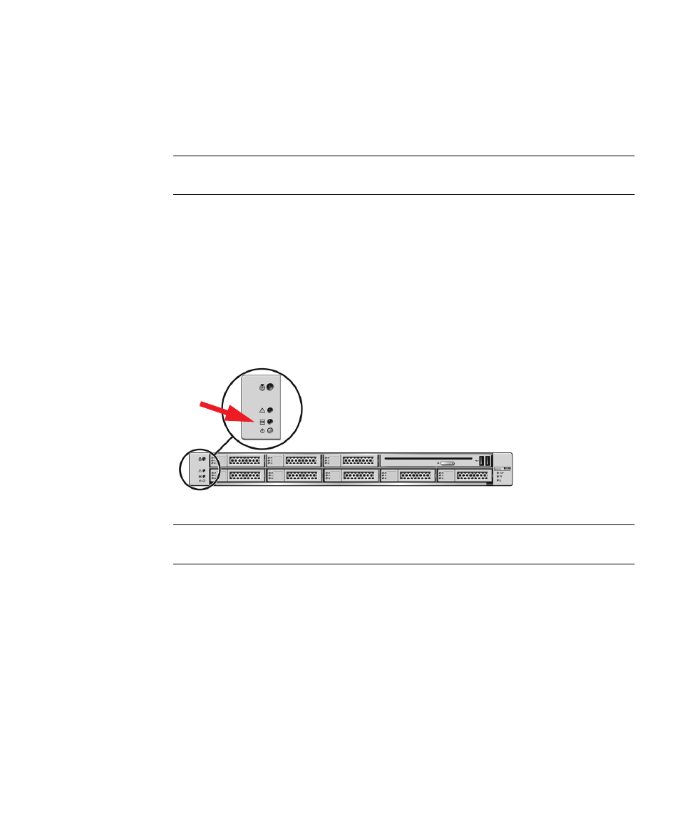
In standby power mode, the Power/OK LED on the front panel flashes,
indicating
that the service processor
(SP)
is working as shown in
FIGURE 3-2
. At this
point,
before
initial configuration, standby power is supplied only to the SP and
power supply fans.
FIGURE 3-2
Front Panel
Power/OK LED
Note –
Do not push the Power button at this time. Do not apply main power to the rest
of the server until you are ready to install a platform operating system
.
3. Connect a serial null modem cable to the serial management/RJ-45 serial port
(4).
See
“Connecting to the LOM Service Processor for the First Time” on page 33
for
more information about viewing system output from a serial console.
4. Connect Ethernet cables to the LOM SP NET MGT Ethernet port (5).
5. Connect Ethernet cables to the RJ-45 GigabitEthernet (LAN) connectors as
needed (6) for OS support.
6. Connect any additional external devices, as required, to the server’s USB (7)
and/or HD-15 Video (8) connectors (optional).