SATO DR300 User Manual
Page 90
DR300 Operator Manual
88
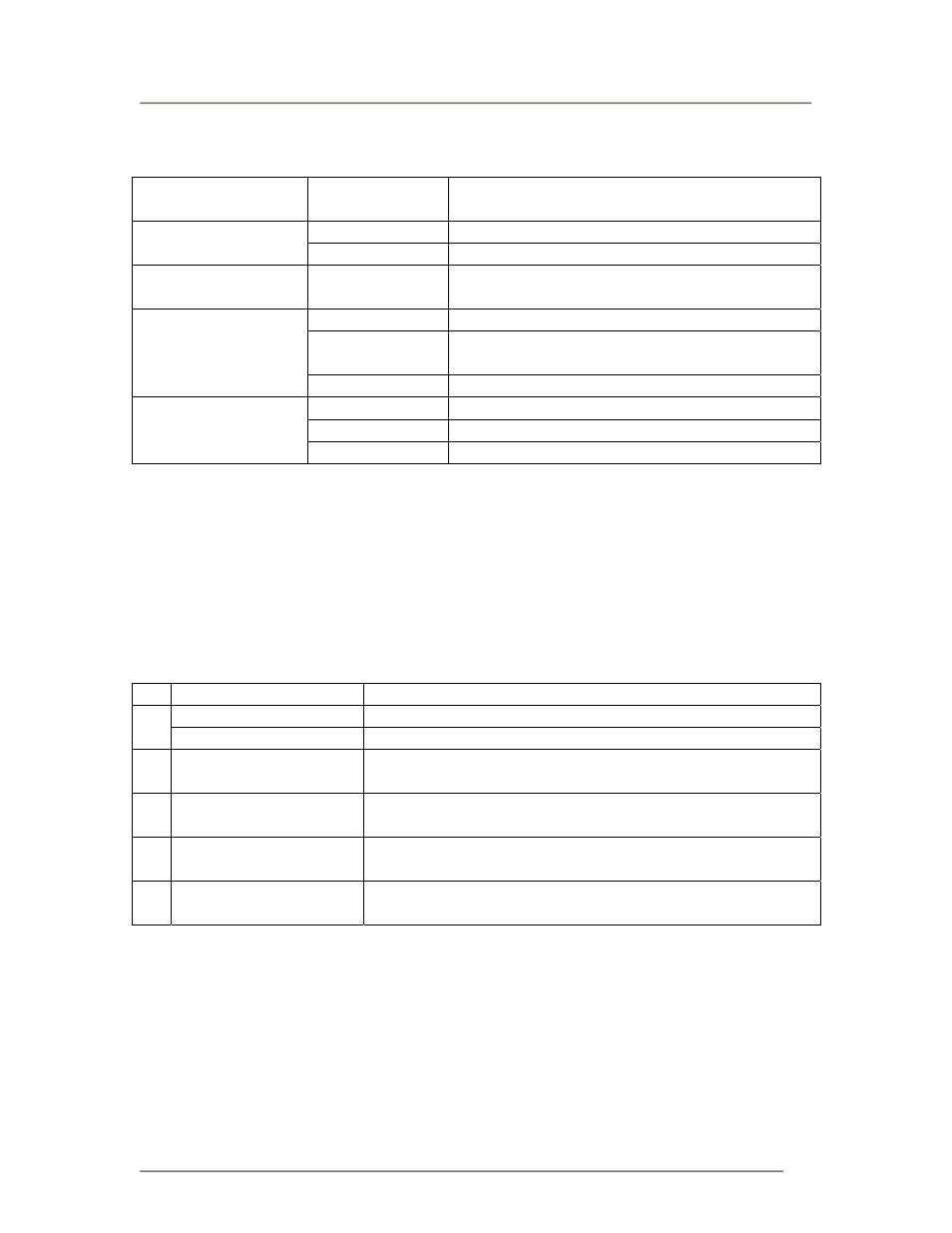
Printer Main Body Operation Unit
LCD Display Unit
8 x 2 lines
LCD display is achieved when touch screen is
not connected.
Feed Key
Paper feeding.
Operation Key
Line Key
Temporary halts printing (print pause)
LED 2
colour
LED
RED : error display
GREEN : On-line
DIPSW 1
Serial interface (setting baud rate, etc)
DIPSW 2
Setting operation mode, etc.
Setting Hex dump function
DIP Switch
DIPSW 3
Setting zero slash and non-standard protocode
PITCH Pitch
adjustment
OFFSET
Cutter, dispense, tear off position adjustment
Variable Control VR
Print darkness adjustment
DIP-Switch Setting
DIP-Switch Setting
DIP-Switch shall be set when printer is off.
Each DIPSW setting is described below.
*All are set to OFF position as factory defaults.
DIPSW 1
No Setting
Content
ON
Data bit No. = 7
1
OFF
Data bit No. = 8
2
3
Separate
Sheet 1
Parity setting (None, Even, Odd)
4 ON
OFF
Stop bit = 2
Stop bit = 1
5
6
Separate
Sheet 2
Baud rate setting (2400, 4800, 9600, 19200)
7
8
Separate
Sheet 3
Protocol setting (Ready/Busy, Xon-Xoff, Status-3)
Appendix A