12 parallel port, floppy and ide drive connections, Parallel port connector – SUPER MICRO Computer 5014C-MF User Manual
Page 59
Chapter 5: Advanced Motherboard Setup
5-21
5-12 Parallel Port, Floppy and IDE Drive Connections
Use the following information to connect the IDE hard disk drive cables.
• A red mark on a wire typically designates the location of pin 1.
• The 80-wire ATA100/66 IDE hard disk drive cable that came with your system
has two connectors to support two drives. This special cable should be used
to take advantage of the speed this new technology offers. The blue connector
connects to the onboard IDE connector interface and the other connector(s) to
your hard drive(s). Consult the documentation that came with your disk drive
for details on actual jumper locations and settings for the hard disk drive.
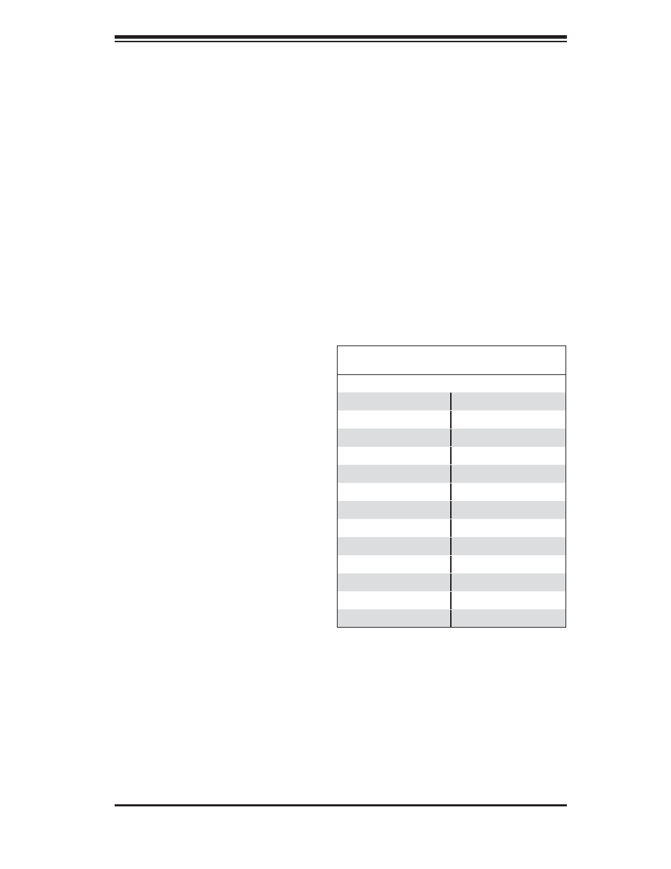
Parallel Port Connector
The parallel port is located on
J11. See the table at right for pin
defi nitions.
Parallel (Printer) Port Connector
Pin Defi nitions (J11)
Pin# Defi nition Pin # Defi nition
1
Strobe-
2
Auto Feed-
3
Data Bit 0
4
Error-
5
Data Bit 1
6
Init-
7
Data Bit 2
8
SLCT IN-
9
Data Bit 3
10
GND
11
Data Bit 4
12
GND
13
Data Bit 5
14
GND
15
Data Bit 6
16
GND
17
Data Bit 7
18
GND
19
ACK
20
GND
21
BUSY
22
Write Data
23
PE
24
Write Gate
25
SLCT
26
NC