16 s, Power led, Wake-on-ring – SUPER MICRO Computer 5014C-MF User Manual
Page 54: Sata led, Serial ports
5-16
S
UPER
S
ERVER 5014C-MF User's Manual
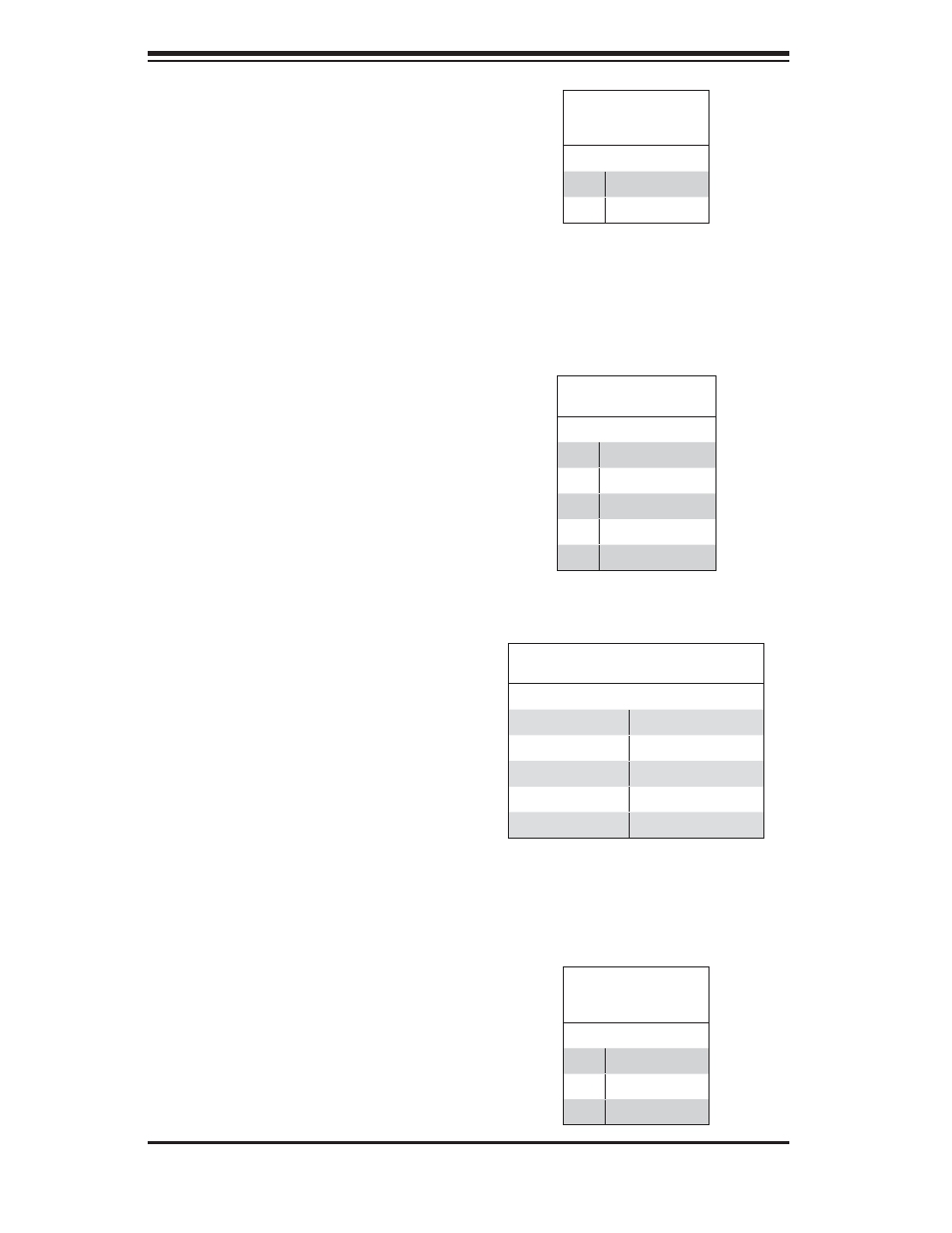
Power LED
The Power LED header is located on
JLED. This header provides LED in-
dication of power being supplied to the
system. See the table on the right for
pin defi nitions.
Wake-On-Ring
The Wake-On-Ring header is designated
JWOR. This function allows your computer
to receive and be "awakened" by an incom-
ing call when in the suspend state. See the
table on the right for pin defi nitions. You
must also have a WOR card and cable to
use this feature.
SATA LED
The SATA LED header is designated
JSLED. This header is used to display
all SATA activity. See the table on the
right for pin defi nitions.
Serial Ports
Two serial ports are included on the
motherboard: COM1 is a port located
under the parallel port and COM2 is
a header located on the motherboard
near the fl oppy connector. See the
table on the right for pin defi nitions.
Wake-On-Ring
Pin Defi nitions
(JWOR)
Pin# Defi nition
1
Ground (Black)
2
Wake-up
SATA LED Pin
Defi nitions (JSLED)
Pin# Defi nition
1
HD Active
2
HD Active
3
HD Active
4
HD Active
5
NC
Note: Pin 10 is included on the header but not on
the port. NC indicates no connection.
Serial Port Pin Defi nitions
(COM1/COM2)
Pin # Defi nition
Pin # Defi nition
1
DCD
6
DSR
2
RXD
7
RTS
3
TXD
8
CTS
4
DTR
9
RI
5
Ground
10
NC
Power LED
Pin Defi nitions
(JLED)
Pin# Defi nition
1
Anode
2
Key
3
Cathode