Group fader command – Sony RS-232C User Manual
Page 29
– 29 –
GROUP FADER : 43[H] 47[H] 46[H] 41[H],42[H] (‘CGFA,B’)
43[H] 47[H] 46[H] 31[H]-36[H] (‘CGF1-2’)
This command is used to set any desired single channel of the GROUP FADER.
Various setups can be memorized in the scene memories by specifying these scene Nos.
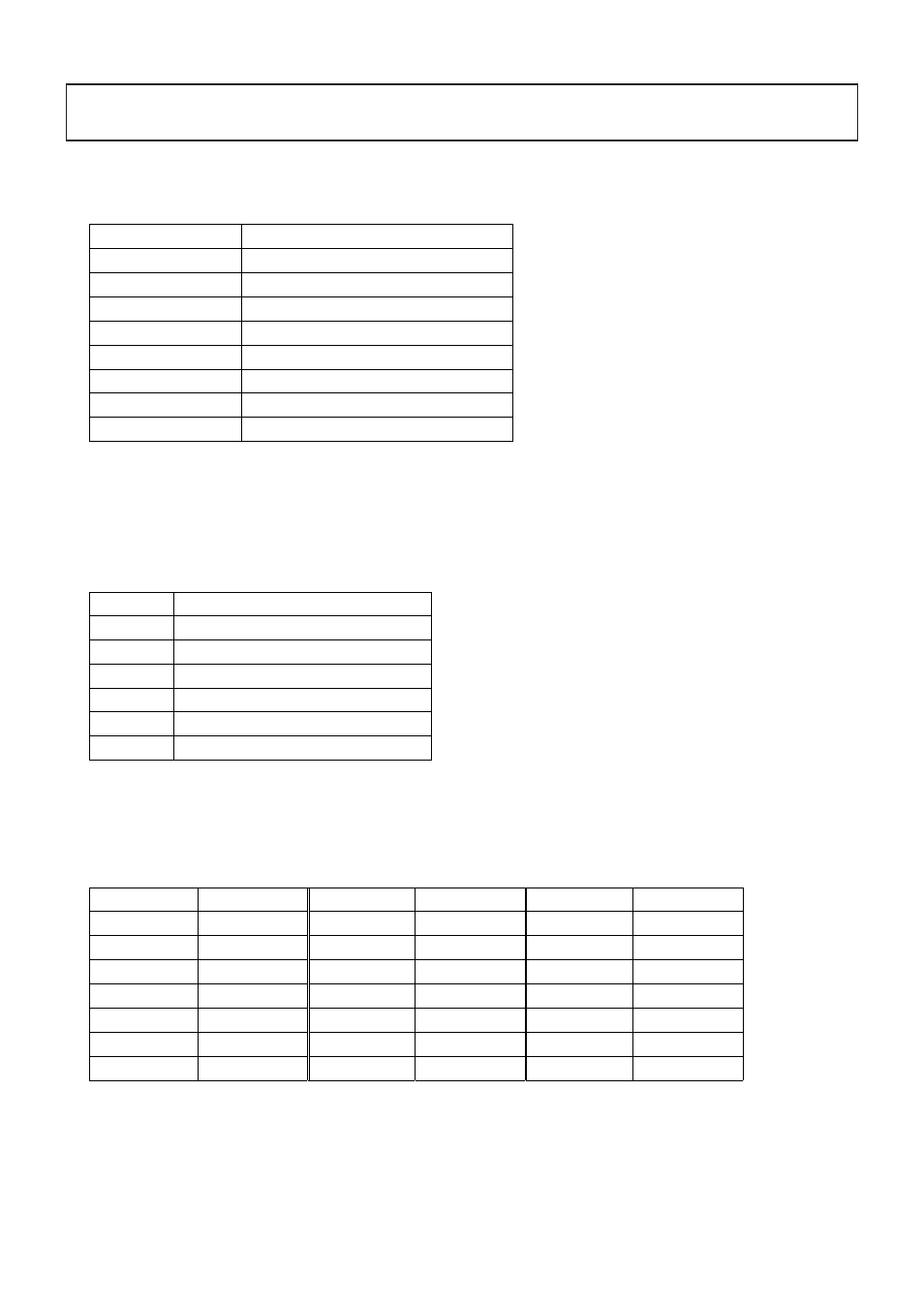
The commands that correspond to the respective channels are shown below.
•
Packet format
43[H] 47[H] 46[H] 41[H] “parameter” 0D[H]
(In the case of MASTER A)
•
Parameter
This parameter consists of the 13-byte data all the time in the order as shown in the table below.
When you specify NONE (30[H] ‘0’) as the scene No. in the 1st byte, you can establish the present setup.
When you specify the scene No.(31[H] (‘1’) to 44[H] (‘D’)), parameters of the subsequent 2nd to 13th bytes are written in the scene
memory.
•
Scene No. (1st byte)
GROUP FADER
Command
MASTER A
43[H] 47[H] 46[H] 41[H] ‘CGFA’
MASTER B
43[H] 47[H] 46[H] 42[H] ‘CGFB’
REMOTE 1
43[H] 47[H] 46[H] 31[H] ‘CGF1’
REMOTE 2
43[H] 47[H] 46[H] 32[H] ‘CGF2’
REMOTE 3
43[H] 47[H] 46[H] 33[H] ‘CGF3’
REMOTE 4
43[H] 47[H] 46[H] 34[H] ‘CGF4’
REMOTE 5
43[H] 47[H] 46[H] 35[H] ‘CGF5’
REMOTE 6
43[H] 47[H] 46[H] 36[H] ‘CGF6‘
byte
Parameter name
1st
SCENE No.
2nd-9th
INDEX
10 th
MIC INPUT FADER
11 th
LINE INPUT FADER
12 th
LINE OUTPUT1-6 FADER
13 th
LINE OUTPUT7,8 FADER
SCENE No.
SCENE No.
SCENE No.
NONE
30[H] (‘0’)
7
37[H] (‘7’)
14
3E[H] (‘>’)
1
31[H] (‘1’)
8
38[H] (‘8’)
15
3F[H] (‘?’)
2
32[H] (‘2’)
9
39[H] (‘9’)
16
40[H] (‘@’)
3
33[H] (‘3’)
10
3A[H] (‘:’)
17
41[H] (‘A’)
4
34[H] (‘4’)
11
3B[H] (‘;’)
18
42[H] (‘B’)
5
35[H] (‘5’)
12
3C[H] (‘<’)
19
43[H] (‘C’)
6
36[H] (‘6’)
13
3D[H] (‘=’)
20
44[H] (‘D’)