Sony PDW-1500 User Manual
Page 66
Ch
apt
er 6
Men
u
s
66
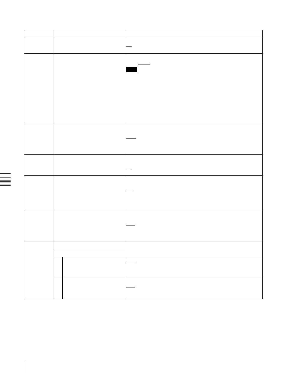
6-3 Extended Menu
Menu items in the 800s, relating to audio control
Item number Item name
Settings
802
DIGITAL AUDIO MUTE IN SHUTTLE
MODE
Set the audio muting conditions during shuttle playback.
off: Not muted.
on: Muted.
803
DIGITAL AUDIO FADE TIME
Specify the time for cross-fade or fade in/out editing of audio signals.
5 ms, 10 ms, 15 ms, 20 ms, 25 ms
a)
, 50 ms
b)
, 85 ms, 115 ms
c)
Note
The cross-fade or fade in/out operation means that the recording is
rewritten from the OUT point for the length specified by this setting. Even
at the minimum 5 ms setting, a length of recording corresponding to a
field is rewritten.
To avoid rewriting, set setup menu item 317 AUDIO EDIT MODE to “cut,”
but in this case there is an audio discontinuity at the edit point. There is
no effect on the recorded video signal.
a) Cross-fade time is 24 ms.
b) Actual value is 49 ms.
c) Actual value is 114 ms.
808
INTERNAL AUDIO SIGNAL
GENERATOR
Select the operation of the internal audio test signal generator.
silnc: Silent signal.
1kHz: 1-kHz, -20 dB FS sine wave signal.
When you select SG as the audio input in the input selection section of
the control panel, the audio test signal generated by the internal audio
test signal generator is input.
815
AUDIO SAMPLING RATE
CONVERTER
Select the mode of operation of the sampling rate converter for AES/
EBU input to channels 1 to 4.
off: No operation
on: Operate.
820
AUDIO OUTPUT CH1/CH2 SELECT Select the signals to be output from the AUDIO OUT 1/3 and AUDIO
OUT 2/4 connectors.
line: Output the audio channel-3 and audio channel-4 signals from the
AUDIO OUT 1/3 and AUDIO OUT 2/4 connectors as they are.
moni: Output the monitor audio L-channel (CH-1) and monitor audio R-
channel (CH-2) signals from the AUDIO OUT 1/3 and AUDIO OUT 2/4
connectors, respectively.
824
ANALOG LINE OUTPUT SELECT
Select the analog audio signals (tracks 1 to 8) to be assigned to audio
output channels 1 and 2.
tr1/2: Tracks 1 and 2 assigned to audio output channels 1 and 2.
tr3/4: Tracks 3 and 4 assigned to audio output channels 1 and 2.
tr5/6: Tracks 5 and 6 assigned to audio output channels 1 and 2.
tr7/8: Tracks 7 and 8 assigned to audio output channels 1 and 2.
827
AES/EBU AUDIO OUTPUT SELECT Select the audio signals to assign to AES/EBU audio output channels.
Sub-item
1
CH1/CH2
tr1/2: Tracks 1 and 2 assigned to audio output channels 1 and 2.
tr3/4: Tracks 3 and 4 assigned to audio output channels 1 and 2.
tr5/6: Tracks 5 and 6 assigned to audio output channels 1 and 2.
tr7/8: Tracks 7 and 8 assigned to audio output channels 1 and 2.
2
CH3/CH4
tr1/2: Tracks 1 and 2 assigned to audio output channels 3 and 4.
tr3/4: Tracks 3 and 4 assigned to audio output channels 3 and 4.
tr5/6: Tracks 5 and 6 assigned to audio output channels 3 and 4.
tr7/8: Tracks 7 and 8 assigned to audio output channels 3 and 4.