4 superimposed text information, Adjusting the text display, Information displayed – Sony PDW-1500 User Manual
Page 37
Chapt
er
3
P
rep
ar
at
ions
37
3-4 Superimposed Text Information
3-4 Superimposed Text
Information
The video signal output from the VIDEO OUT 2 (SUPER)
connector or the SDI OUT 2 (SUPER) connector contains
superimposed text information, including time code, menu
settings, and alarm messages.
Adjusting the text display
You can adjust the position, size and type of the
superimposed text using basic menu items 002, 003, 005,
009, and 011.
For details, see 6-2-1 “Items in the Basic Setup Menu”
(page 54).
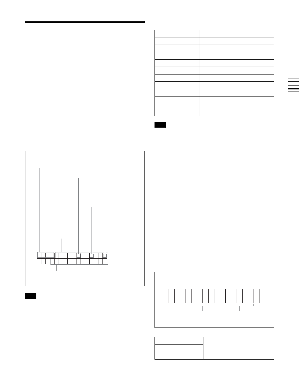
Information displayed
Note
The display shown above corresponds to the factory
default settings of the unit. You can change the type of
information to be displayed in the lower line of the display
by changing the setting of basic menu item 005
“DISPLAY INFORMATION SELECT.”
For details, see 6-2-1 “Items in the Basic Setup Menu”
(page 54).
a Type of time data
Note
If the time data or user's bits cannot be read correctly,
they will be displayed with an asterisk. For example,
“T*R”, “U*R”, “T*R.” or “U*R.”.
b Time code reader drop frame mark (for 525-line
mode only)
“.”: Indicates drop frame mode
“:”: Indicates non-drop-frame mode
c Time code generator drop frame mark (for 525-line
mode only)
“.”: Indicates drop frame mode (factory preset)
“:”: Indicates non-drop-frame mode
d VITC field mark
“ ” (blank): Fields 1 and 3 (for 525/60 mode) or fields 1, 3,
5 and 7 (for 625/50 mode)
“ * ”: Fields 2 and 4 (for 525/60 mode) or fields 2, 4, 6 and
8 (for 625/50 mode)
e Operation mode
The field is divided into two blocks as shown below.
• Block A displays the operation mode.
• Block B displays the servo lock status or search speed.
T C R
0 0 : 0 4 . 4 7 . 0 7 *
P L A Y
L O C K
5
Operation mode
1
Type of time data
2
Time code reader drop frame
mark (for 525-line mode only)
3
Time code generator drop
frame mark (for 525-line
mode only)
4
VITC field mark
Time data
Display
Meaning
CNT
Counter data
TCR
TC reader time code data
UBR
TC reader user bits data
TCR.
VITC reader time code
UBR.
VITC reader user bits data
TCG
TC generator time code
UBG
TC generator user bits data
IN
IN point time data
OUT
OUT point time data
DUR
Duration between IN point and OUT
point
Display
Operation mode
Block A
Block B
DISC OUT
Disc is not loaded.
B
A