Sony PDW-1500 User Manual
Page 23
Chap
ter
2
mes
a
nd F
unc
tions
of
P
a
rt
s
23
2-1 Front Panel
Reverse direction high-speed search: Hold down the
PLAY button, and press this button. A high-speed
search in the reverse direction is carried out.
Displaying the first frame of the first clip: Hold down
the SHIFT button, and press this button.
b PLAY (playback) button
To start playback, press this button, turning it on.
c NEXT button
Press this button, turning it on, to jump to the next clip, and
show the first frame.
This button is also used together with other buttons for the
following operations.
Forward direction high-speed search: Hold down the
PLAY button, and press this button. A high-speed
search in the forward direction is carried out.
Displaying the last frame of the last clip: Hold down the
SHIFT button, and press this button.
d STOP button
To stop recording or playback, press this button, turning it
on. The frame at the stop point appears.
e REC (record) button
To start recording, hold down this button, and press the
PLAY button. The recording takes place on an unrecorded
part of the disc.
To stop recording, press the STOP button.
This creates a clip of the recorded portion.
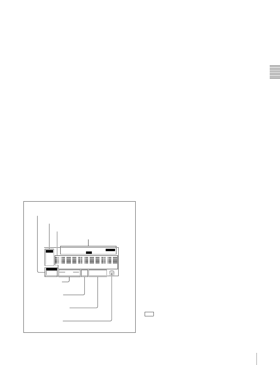
5 Status display section
a MONITOR (audio monitor channel selection)
display
This shows the audio channels selected by the AUDIO
MONITOR SEL button(see page 21). The displayed
channel audio is output from the PHONES jack on the
front panel and the AUDIO MONITOR OUT connector on
the rear panel, according to the setting of the MONITOR
switch (see page 21).
1/2: channels 1 (left) and 2 (right)
3/4: channels 3 (left) and 4 (right)
5/6: channels 5 (left) and 6 (right)
7/8: channels 7 (left) and 8 (right)
b INPUT (video input signal) display
Shows the currently selected video input signal.
i.LINK: i.LINK compliant DVCAM format digital signal
SDI: SDI video signal
CMPST: Composite video signal
SG: Test video signal from the internal signal generator
Make the video signal input selection with the VIDEO
INPUT SEL button (see page 20).
c Time data display
Normally, this shows the disc playback time, time code, or
user bit information, as selected by the COUNTER
SELECT button (see page 20) and extended menu item
629 “TC SELECT.”
It is also used for error messages, setup menus, and other
displays.
d Indicators above the time data display
There are the following indicators.
REMOTE (9P/i.LINK) indicator: This shows “9P” or
“i.LINK” as follows.
• 9P: When extended menu item 214 “REMOTE
INTERFACE” is set to “9PIN.”
• i.LINK: When extended menu item 214 “REMOTE
INTERFACE” is set to “i.LINK.”
COUNTER indicator: This lights when a counter value
(hours, minutes, seconds, and frames, resettable) is
displayed in the time data display.
TC/VITC (time code type) indicator: This lights when
the COUNTER SELECT button (see page 20) is set to
TC. The time data display shows the time code.
When extended menu item 629 “TC SELECT” is set
to “TC,” this shows “TC,” and when “VITC” is
selected, it shows “VITC.”
UB/VIUB (user bit type) indicator: This lights when the
COUNTER SELECT button is set to UB. The time
data display shows the user bits.
When extended menu item 629 “TC SELECT” is set
to “TC,” this shows “UB,” and when “VITC” is
selected it shows “VIUB.”
indicator: This lights in the following cases.
• In playback mode, when VITC is being read.
(Regardless of what the time data display is
showing.)
HOURS
MINUTES
SECONDS
FRAMES
VITC
VITC
COUNTER
REC INH
VIUB
EDIT
KEY INH
REMOTE [9P iLINK]
INPUT
i.LINK
SDI
1/2
5/6
3/4
7/8
625
525
IMX[50 40 30]
DVCAM
4 8 CH
18 24 BIT
CMPST
Y-R,B
SG
ALARM
MONITOR
AUDIO
1
MONITOR display
2
INPUT display
3
Time data display
4
Indicators above the time data display
5
AUDIO indicators
6
525/625 indicator
8
Disc loaded mark
7
IMX/DVCAM indicator
VITC