Sony PDW-1500 User Manual
Page 21
Chap
ter
2
mes
a
nd F
unc
tions
of
P
a
rt
s
21
2-1 Front Panel
To display the thumbnails of essence mark frames (frames
with an essence mark attached), hold down the SHIFT
button, and press this button. The essence mark selection
menu appears. Select the desired type of essence mark, and
the corresponding essence mark frames appear in
thumbnails. Press once more, turning the button off, to
return to a whole-screen display.
l Disc slot and EJECT button
Insert a disc in the disc slot. To remove the disc, press the
EJECT button.
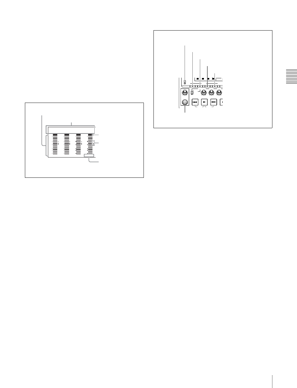
1 Audio level meter section
a Audio level meters
Depending on the setting of the AUDIO METER SEL
button (see page 21), these show the audio recording levels
(during recording) or audio playback levels (during
playback) of channels 1 to 4 or channels 5 to 8. If an audio
level exceeds 0 dB, the OVER indicator lights.
By means of a maintenance menu setting, you can display
a reference level indicator (“-”) to the right of each meter
when recording.
For details of the maintenace menu, see 6-4 “Maintenance
Menu” on page 70.
b Audio input display
For each channel, the following indicators light to show
the type of the selected audio input signal.
ANA: Analog audio signal
SDI: SDI audio signal
AES/EBU: AES/EBU format digital audio signal
SG: Audio test signal generated by the internal signal
generator
Make the audio input signal selection with the AUDIO
INPUT SEL button (see page 22).
2 Audio settings section
a MONITOR switch
Of the two channels (left and right) selected by the AUDIO
MONITOR SEL button (see next item), selects whether
both or one is monitored.
L: The left channel audio is output from the PHONES jack
and the AUDIO MONITOR OUT connector.
R: The right channel audio is output from the PHONES
jack and the AUDIO MONITOR OUT connector.
MIX: Stereo audio is output from the PHONES jack.
Monaural audio, the left and right channels mixed, is
output from the AUDIO MONITOR OUT connector.
b AUDIO MONITOR SEL (selection) button
Of the up to eight audio signal channels, the audio of the
two channels (left and right channels in the case of a stereo
output) selected by this button can be monitored with the
PHONES jack on the front panel and the AUDIO
MONITOR OUT connector on the rear panel.
Pressing this button cycles through the first two of the
following channel combinations (in four-channel mode) or
all of the four channel combinations (in eight-channel
mode).
• Channels 1 (left) and 2 (right)
• Channels 3 (left) and 4 (right)
• Channels 5 (left) and 6 (right)
• Channels 7 (left) and 8 (right)
In the status display section, the MONITOR display (see
page 23) changes to reflect the selection.
The factory default is for channels 1 (left) and 2 (right) to
be selected.
You can select whether to monitor both of the selected
channels or only one, using the MONITOR switch (see
page 21).
c AUDIO METER SEL (selection) button
When using MPEG IMX format in eight-channel mode,
select whether the audio level meters should display
channels 1 to 4 or channels 5 to 8.
OVER
dB
-12
-20
-30
-40
-60
0
CH-
15
BQ DATA
ANA SDI
AE8/EBU
OVER
dB
-12
-20
-30
-40
-60
0
CH-
26
BQ DATA
ANA SDI
AE8/EBU
OVER
dB
-12
-20
-30
-40
-60
0
CH-
37
BQ DATA
ANA SDI
AE8/EBU
OVER
dB
-12
-20
-30
-40
-60
0
CH-
48
BQ DATA
ANA SDI
AE8/EBU
1
Audio level meters
2
Audio input display
OVER indicator
Reference level
indicator
Channel display
REC
VARIABLE
PRESET
PB
L
MIX
R
MONITOR
PHONES
TOP
F REV
F FWD
END
PREV
NEXT
PLAY
AUDIO
MONITOR SEL METER SEL
INPUT CH
INPUT SEL
VIDE
INPUT
ST
ALL/CH-1
CH-2
CH-3
40
-60
CH-
15
40
-60
CH-
26
40
-60
CH-
37
40
-60
CH-
48
1/2
5/6
3/4
7/8
4
MONITOR
1
MONITOR switch
2
AUDIO MONITOR SEL button
3
AUDIO METER SEL button
4
AUDIO INPUT CH button
5
AUDIO INPUT SEL button
6
PHONES jack and volume control knob