2 rear panel, 1 analog audio signal inputs/outputs – Sony PDW-1500 User Manual
Page 26
C
h
ap
te
r 2
N
a
m
e
s
a
n
d
F
u
nc
tion
s
of
P
a
rt
s
26
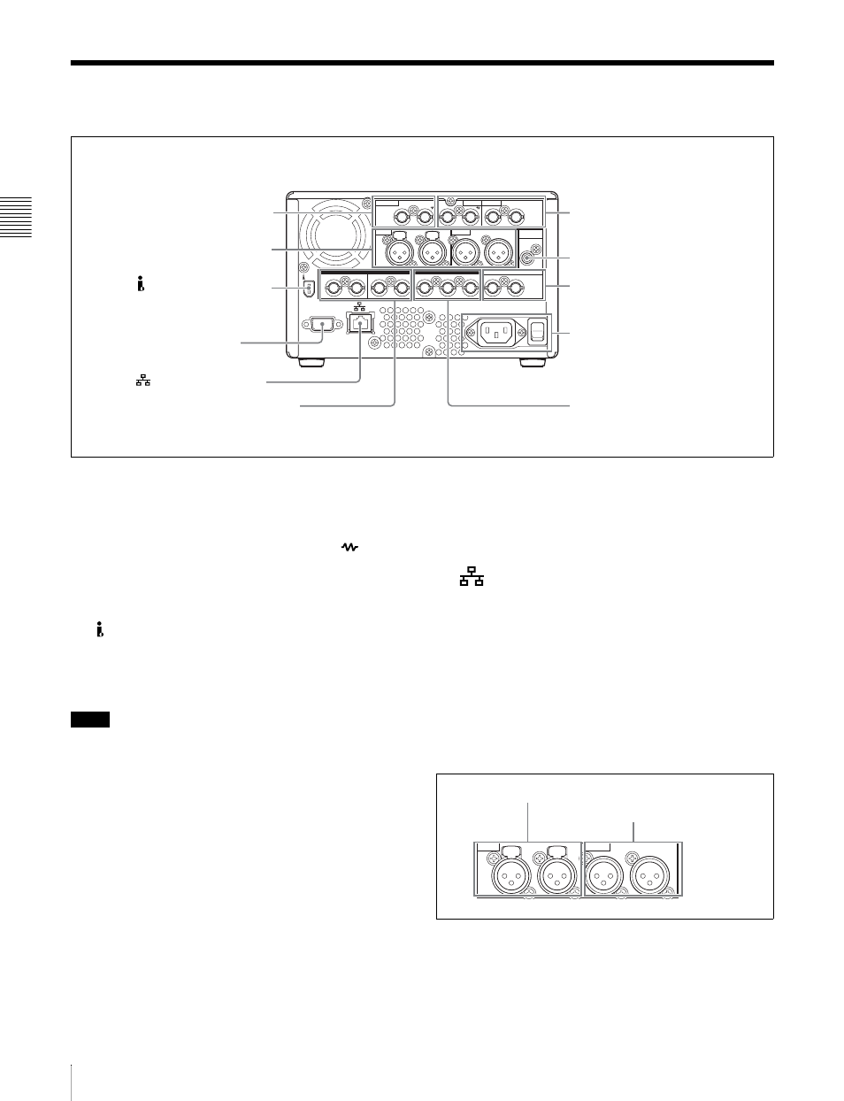
2-2 Rear Panel
2-2 Rear Panel
a REF. VIDEO IN (reference video signal input)
connectors (BNC type)
The two connectors form a loop-through connection; when
a reference video signal is input to the left connector, the
same signal is input from the right connector (
) to a
connected device. When no connection is made to the right
connector, the left connector is automatically terminated
with an impedance of 75 ohms.
b
S400 (i.LINK) connector (6-pin, IEEE1394
compliant)
Connect a DV device, computer, or similar, using a DV
cable.
Notes
• When the PDW-1500 is connected to a device with a 6-
pin DV connector by a DV cable, before unplugging the
DV cable, first power off the device and disconnect the
power plug from the outlet. If the DV cable is unplugged
with the device power plug still connected, a current
from an excessive voltage (8 to 40 V) output from the
DV connector of the device flows into the PDW-1500.
This may cause a failure of the PDW-1500.
• When connecting the PDW-1500 to a device with a 6-pin
DV connector, connect to the 6-pin DV connector of the
other device first.
• Except in playback mode, if you are monitoring the
audio signal output from this connector on another
device, the audio signal may sound differently from the
audio signal played back on the PDW-1500.
c REMOTE (remote control signal) connector (D-
sub 9-pin)
To control the PDW-1500 from a controller or VTR
supporting the RS-422A Sony 9-pin VTR protocol,
connect the device to this connector.
d
(network) connector (RJ-45 type)
This is a 10Base-T/100Base-TX/1000Base-T connector
for network (Ethernet) connection.
e AUDIO MONITOR OUT connector (RCA-pin)
This outputs an audio signal for monitoring.
The monitored channel is selected by the combination of
the AUDIO MONITOR SEL button (see page 21) and
MONITOR switch (see page 21).
1 Analog audio signal inputs/outputs
a AUDIO IN (analog audio signal input) 1/3, 2/4
connectors (XLR 3-pin, female)
These are analog audio signal input connectors.
With the AUDIO INPUT SEL button (see page 22), you
can select whether the signal input to connector 1/3 is
1
2
(SUPER)
1/3
2/4
1/2
IN
3/4
IN
OUT 1
2 (SUPER)
1/2
OUT
3/4
IN
OUT
1/3
2/4
AUDIO IN
DIGITAL AUDIO (AES/EBU)
REMOTE
S400
SDI
TIME CODE
AUDIO OUT
AUDIO
MONITOR OUT
VIDEO IN
REF.VIDEO IN
VIDEO OUT
1
REF. VIDEO IN connectors
1 Analog audio signal inputs/
outputs (see page 26)
2
S400 (i.LINK) connector
3
REMOTE connector
4
(network) connector
2 Digital audio signal inputs/outputs
(see page 27)
3Analog video signal inputs/
outputs (see page 27)
4Time code inputs/outputs
(see page 27)
5
AUDIO MONITOR OUT connector
6 SDI signal inputs/
outputs (see page 28)
5 Power supply section
(see page 28)
1/3
2/4
1/3
2/4
AUDIO IN
AUDIO OUT
1
AUDIO IN 1/3, 2/4 connectors
2
AUDIO OUT 1/3, 2/4 connectors