Connecting to the console port, Wiring map for serial cable, Table 3-1 serial cable wiring -13 – SMC Networks SMC TigerStack III SMC6826MPE User Manual
Page 53: Figure 3-9, Serial port (db-9 dte) pin-out -13
C
ONNECTING
TO
THE
C
ONSOLE
P
ORT
3-13
Connecting to the Console Port
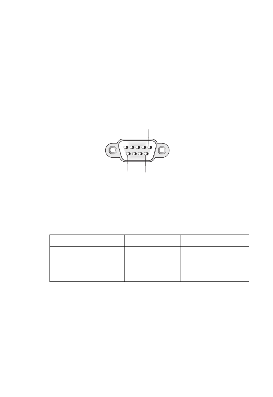
The DB-9 serial port on the switch’s front panel is used to connect to the
switch for out-of-band console configuration. The command-line
configuration program can be accessed from a terminal or a PC running a
terminal emulation program. The pin assignments used to connect to the
serial port are provided in the following table.
Figure 3-9 Serial Port (DB-9 DTE) Pin-Out
Wiring Map for Serial Cable
Table 3-1 Serial Cable Wiring
The serial port’s configuration requirements are as follows:
•
Default Baud rate—9,600 bps
•
Character Size—8 Characters
•
Parity—None
Switch’s 9-Pin Serial Port
Null Modem
PC’s 9-Pin DTE Port
2 RXD (receive data)
<----------------------
3 TXD (transmit data)
3 TXD (transmit data)
---------------------->
2 RXD (receive data)
5 SGND (signal ground)
------------------------
5 SGND (signal ground)
No other pins are used.
1
5
6
9