Connecting switches in a stack, Twisted-pair devices -1, Figure 3-7 – SMC Networks SMC TigerStack III SMC6826MPE User Manual
Page 50: Connecting switches in a stack -10, 10 connecting switches in a stack, Nstalling, Witch, Slave, Slave stack master
I
NSTALLING
THE
S
WITCH
3-10
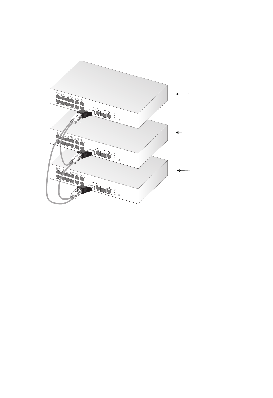
Connecting Switches in a Stack
Figure 3-7 Connecting Switches in a Stack
Note: The stacking transceiver must only be installed in the port 25 SFP
slot.
To connect up to eight switches in a stack, perform the following steps:
1. Install SFP stacking transceivers into the port 25 slot for each switch
in the stack.
2. Plug one end of a stack cable into the Tx (top) port of the top unit
3. Plug the other end of the stack cable into the Rx (bottom) port of the
next unit.
4. Repeat steps 1 and 2 for each unit in the stack. Form a simple chain
starting at the Tx port on the top unit and ending at the Rx port on the
bottom unit (stacking up to 8 units).
Slave
Slave
Stack Master
13
14
15
16
17
18
19
20
21
22
23
24
26
Link/A
ct
PoE
25
26
PWR
Diag
Stackin
g
Mode
PoE/L
ink
25
13
14
23
24
13
14
15
16
17
18
19
20
21
22
23
24
26
Link/A
ct
PoE
25
26
PWR
Diag
Stackin
g
Mode
PoE/L
ink
25
13
14
23
24
Tx
Rx
13
14
15
16
17
18
19
20
21
22
23
24
26
Link/A
ct
PoE
25
26
PWR
Diag
Stackin
g
Mode
PoE/L
ink
25
13
14
23
24
13
14
15
16
17
18
19
20
21
22
23
24
26
Link/A
ct
PoE
25
26
PWR
Diag
Stackin
g
Mode
PoE/L
ink
25
13
14
23
24
Tx
Rx
13
14
15
16
17
18
19
20
21
22
23
24
26
Link/A
ct
PoE
25
26
PWR
Diag
Stackin
g
Mode
PoE/L
ink
25
13
14
23
24
13
14
15
16
17
18
19
20
21
22
23
24
26
Link/A
ct
PoE
25
26
PWR
Diag
Stackin
g
Mode
PoE/L
ink
25
13
14
23
24
Tx
Rx