Port and system status led indicators, Mode poe/link button -9, Table 1-1 port status led indicators -5 – SMC Networks SMC TigerStack III SMC6826MPE User Manual
Page 25: Figure 1-2, Port led indicators -5, 5 port and system status led indicators
D
ESCRIPTION
OF
H
ARDWARE
1-5
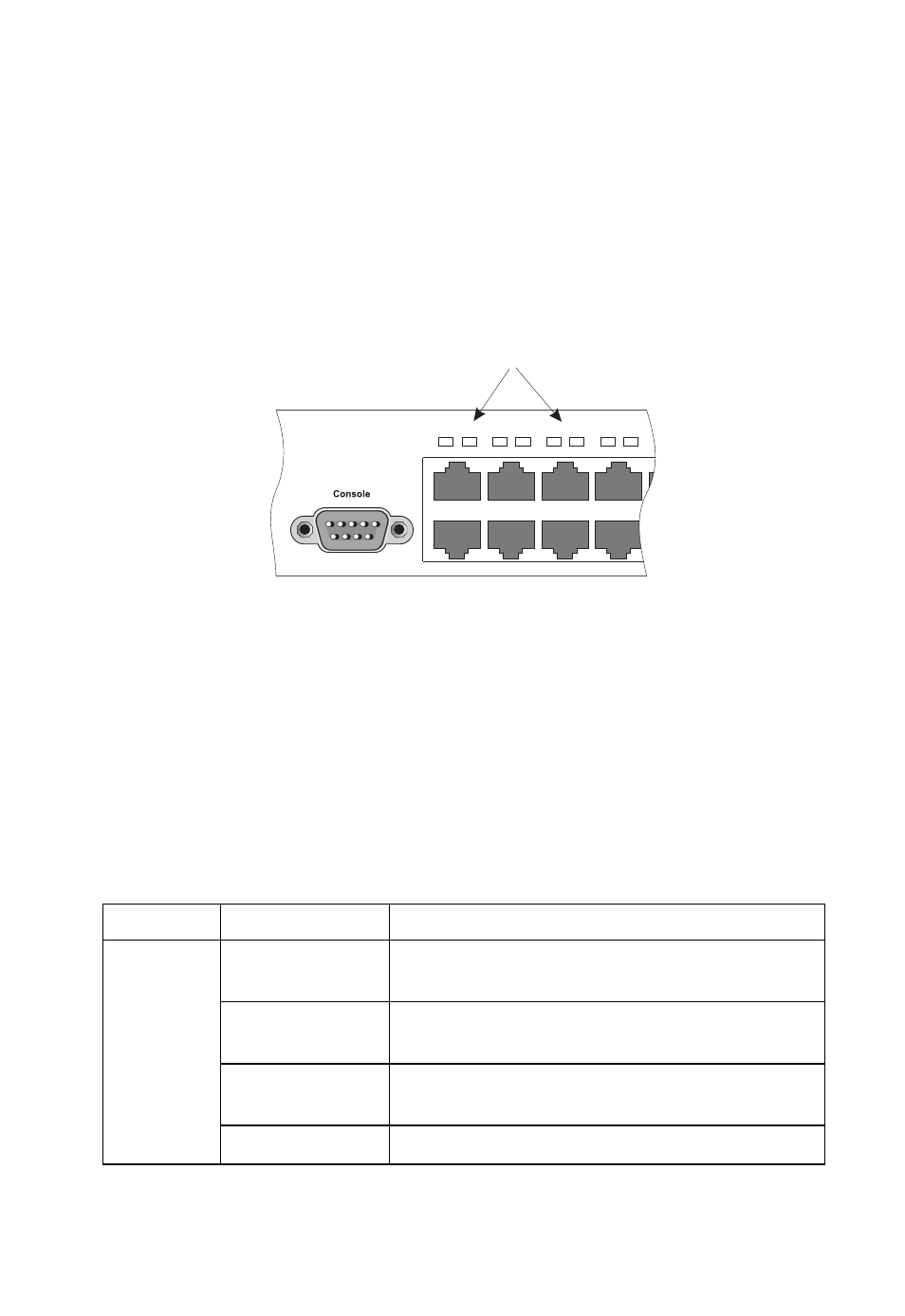
Port and System Status LED Indicators
The switch base unit also includes a display panel for key system and port
indications that simplify installation and network troubleshooting. The
LED indicators, which are located on the front panel for easy viewing, are
shown below and described in the following tables.
Figure 1-2 Port LED Indicators
The port status LED indicators have two display modes; Link and PoE.
The Link mode displays the link status and network activity on each port.
The PoE mode displays the PoE power status on each port. Use the Mode
Link/PoE button (see “Mode PoE/Link Button” on page 1-9) on the
front panel to toggle between the two display modes. The current mode is
indicated by the Link/Act and PoE system LED indicators.
Table 1-1 Port Status LED Indicators
LED
Condition
Status
1~24
(Link/Act
Mode)
On/Flashing
Green
Port has established a valid 100 Mbps network
connection. Flashing indicates activity.
On/Flashing
Amber
Port has established a valid 10 Mbps network
connection. Flashing indicates activity.
Alternate Green/
Amber
Port has been disabled by the administrator.
Off
There is no valid link on the port.
Port Status LEDs
1
2
3
4
5
6
7
8
9
1
2