9 multi roi mode (multi region of, Mode and functions matrix, At-200ge – JAI AT-200GE User Manual
Page 52
AT-200GE
- 50 -
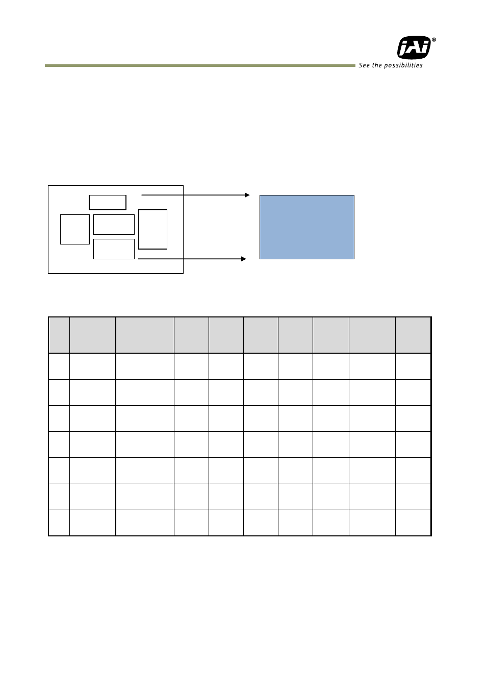
9.7.9 Multi ROI mode (Multi Region of Interest)
In this trigger mode, up to 5 ROIs located on one image can be output by one trigger input.
By using this mode, the data stream can be smaller. Each ROI can be overlapped.
Please note that if the accumulated data size is bigger than the data size of 1 frame, the
frame rate will be reduced.
As explained in section 9.3.3, partial scan mode is associated with ROI and in the case of
figure 51, the start line of ROI 2 and the end line of ROI 4 would define a partial scan area.
Fig. 51 Multi ROI conceptual drawing
9.8. Mode and functions matrix
ID
Mode
Shutter
Programmable/
Exposure Abs
Auto
shutter
V
Binning
Partial
scan
Smear
less
Multi
ROI
LVAL
Sync/
Async
Auto Iris
output
0x00 Continuous
○
○
○
○
Ч
Ч
---
○
0x01
EPS
○
×
○
○
○
○
Auto
×
0x02
PWC
---
×
○
○
○
○
Auto
×
0x04
RCT
○
○
○
○
○
○
Async
only
○
0x09
Sequential
EPS
○
Ч
○
○
○
Ч
Auto
×
0x11
EPS
Delayed
readout
○
Ч
○
○
○
Ч
Auto
×
0x12
PWC
Delayed
Readout
---
Ч
○
○
○
Ч
Auto
×
Note: 1. Trigger mode can be set by writing ID value in register 0xA040.
2. In trigger modes from ID 0x09 to ID 0x12, if trigger mode is changed, set “Acquisition Stop”
and then set continuous mode(ID 0x00) first and change to required trigger mode. For
instance, it is not possible to change directly from ID 0x09 sequential EPS mode to 0x11 EPS
delayed readout mode.
ROI
1
ROI 2
ROI
3
ROI 4
ROI 5
Partial scan area