Locations and functions, At-200ge – JAI AT-200GE User Manual
Page 10
AT-200GE
- 8 -
4. Locations and Functions
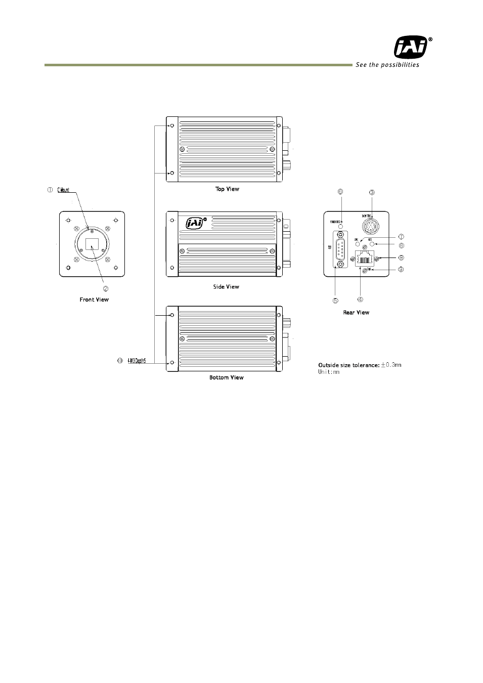
4.1. Locations and Functions
1. Lens mount
Lens mount of C-mount type. *1)
2. CCD sensor
1/1.8 inch CCD
3. RJ-45 connector
GigE Vision interface with thumb screws
4. 12-pin connector
DC+12V, Trigger IN and EEN out
5. D-sub 9-pin connector
LVDS IN and TTL IN and OUT
6. LED
Power and trigger indications
7. LINK
Indication for Network connection
8. ACT
Indication for GigE communication
9.Holes for RJ-45 thumbscrews
Vertical type and horizontal type (*2)
10.Mounting holes
M3, max length 5mm (*3)
*1) Note:
Applicable C-mount lens should be designed for 3-CCD cameras. Rear protrusion on
C-mount lens must be less than 4mm.
Be advised: when using a lens with the iris diaphragm fully open, vignetting on corners
may occur.
*2) Note: When an RJ-45 cable with thumb screws is connected to the camera, please do not
excessively tighten screws by using a driver. The RJ-45 receptacle on the camera might
be damaged. For security, the strength to tighten screws is less than 0.147 Newton
meter (Nm). Tightening by hand is sufficient in order to achieve this.
*3) Note:
The tripod adapter plate MP-41 can be used.
Fig. 1. Locations