Server board connector and component locations – Intel SHG2 User Manual
Page 11
Description 11
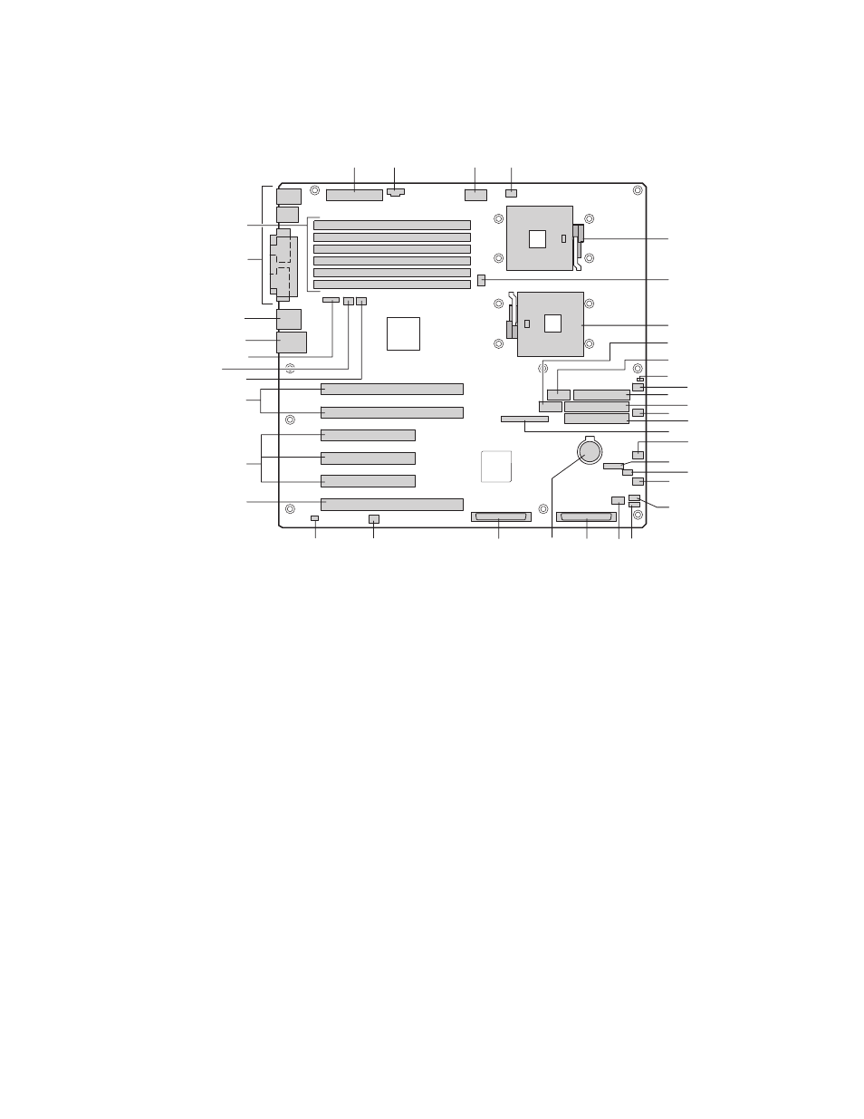
Server Board Connector and Component Locations
A
B
C
D
E
F
G
H
I
J
K
L
M
N
O
P
Q
R
S
T
U
V
X
W
Y
Z
AA
BB
CC
DD
EE
FF
GG
HH
II
JJ
KK
LL
OM14357
A
Primary Processor Socket (CPU1)
T
LVD SCSI B
B CPU2
Fan
U Battery
C
Secondary Processor Socket (CPU2)
V
LVD SCSI A
D
Front Panel USB
W
Jumper block CN53
E
Serial B
X
Chassis Intrusion
F
Jumper Block CN27
Y
PCI-X 64-bit/133 MHz
G
System Fan 5
Z
PCI 32-bit/33 MHz
H
Floppy disk drive connector
AA
PCI-X 64-bit/100 MHz
I
Secondary IDE
BB
System Fan 1
J
System Fan 6
CC
System Fan 2
K
Primary IDE
DD
ICMB
L
Front Panel connector
EE
NIC1 (10/100)
M IPMB
FF
NIC2 (Gbit)
N
Jumper Block CN43
GG
System I/O connectors
O
System Fan 3
HH
DIMMs
P
System Fan 4
II
Main Power
Q
HSBP B
JJ
Aux Sig
R
HSBP A
KK
+12 V CPU Power
S
HDD LED Connector
LL
CPU1 Fan
Figure 2. Server Board Connector and Component Locations
- 41210 (64 pages)
- 8xC251TQ (20 pages)
- ENTERPRISE PRINTING SYSTEM (EPS) 4127 (84 pages)
- U3-1L (20 pages)
- 80960HA (104 pages)
- X58 (54 pages)
- ESM-2850 2047285001R (91 pages)
- ATOM US15W (54 pages)
- D915GVWB (4 pages)
- XP-P5CM-GL (28 pages)
- AX965Q (81 pages)
- CORETM 2 DUO MOBILE 320028-001 (42 pages)
- CV700A (63 pages)
- 80C188EA (50 pages)
- X25-M (28 pages)
- XP-P5IM800GV (26 pages)
- IB868 (60 pages)
- D865GVHZ (88 pages)
- IB865 (64 pages)
- Altera P0424-ND (1 page)
- 8086-2 (30 pages)
- IXDP465 (22 pages)
- IWILL P4D (104 pages)
- GA-8I955X PRO (88 pages)
- FSB400 (PC2100) (96 pages)
- D845GLAD (4 pages)
- NAR-3041 (1 page)
- 87C196CA (136 pages)
- G52-M6734XD (74 pages)
- A96134-002 (10 pages)
- Express Routers 9000 (8 pages)
- 82540EP (45 pages)
- D865GLC (94 pages)
- IB850 (69 pages)
- MB898RF (62 pages)
- Arima LH500 (78 pages)
- V09 (33 pages)
- I/O Processor (22 pages)
- M600 (110 pages)
- SE7520JR2 (63 pages)
- SERVER BOARD S5520HCT (30 pages)
- Extensible Firmware Interface (1084 pages)
- GA-8IPXDR-E (70 pages)
- D845EBG2 (4 pages)
- AW8D (80 pages)