Replacing the top cover, Replacing the led assembly – Intel Express 5800/120Ld User Manual
Page 117
Dissasembly and Reassembly 4-45
Replacing the LED Assembly
The LED Assembly includes the DC Power ON/OFF LED, the Intrusion LED,
the Disk Fault LED, and the Sleep Status LED. Each of the four LEDs is
mounted on a front panel bracket and is attached to a single cable harness that
connects to the system board.
1. Power off the system and ensure it is disconnected from the AC power
source.
2. Open and remove the front door and remove the left side panel as described
earlier in this chapter.
3. Tag and disconnect the LED Assembly cable connected to the system board.
See Figure 1-5, F for correct location.
4. The LED Assembly cables are threaded through three cable clamps. The
cable clamps may be released by pressing the tab located below the head of
the clamp. If any of the cable clamps cannot be released, carefully cut the
clamps to allow access to the cables.
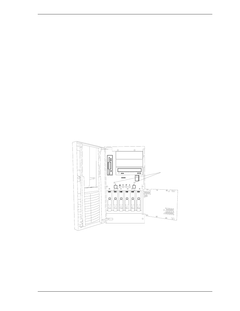
5. Remove the two screws securing the LED Assembly mounting bracket to
the front of the chassis. See Figure 4-43, A. Position the assembly outside of
the system.
0
1
2
3
4
5
A
Figure 4-43. LED Assembly Mounting Screws
6. Note the wire color codes and position of the four LEDs mounted in the
LED sockets of the mounting bracket.
7. Squeeze the front tabs of the LED sockets and push the LED sockets out the
front of the mounting bracket. See Figure 4-44.