2 power-down sequence – Intel SE8500HW4 User Manual
Page 71
Intel® Server Board Set SE8500HW4
Electrical Specifications
Revision 1.0
Intel order number D22893-001
59
Table 34. Typical Power-Up Timings
Ref
Description
Max Typical
Min
t1
Time from front-panel power button push to BMC asserting the power button to the
chipset. This includes the private store update for Pwr State change, which is on the
order of 500ms + overhead, which accounts for other task completion time like Init
Agent. BMC also debounces signal for 50ms.
2s 1s
50ms
t2
Time from BMC asserting power button to chipset, until chipset responds with
SLP_S5.
– 16ms
60µs
t3
Time from when SLP_S5 is asserted, to when BMC asserts PS_ON_L to complete
system power-on.
1s 97ms 50ms
t4
Time from when BMC has completed driving its power-on signals, to when system
asserts power good back to BMC.
– 500ms
250ms
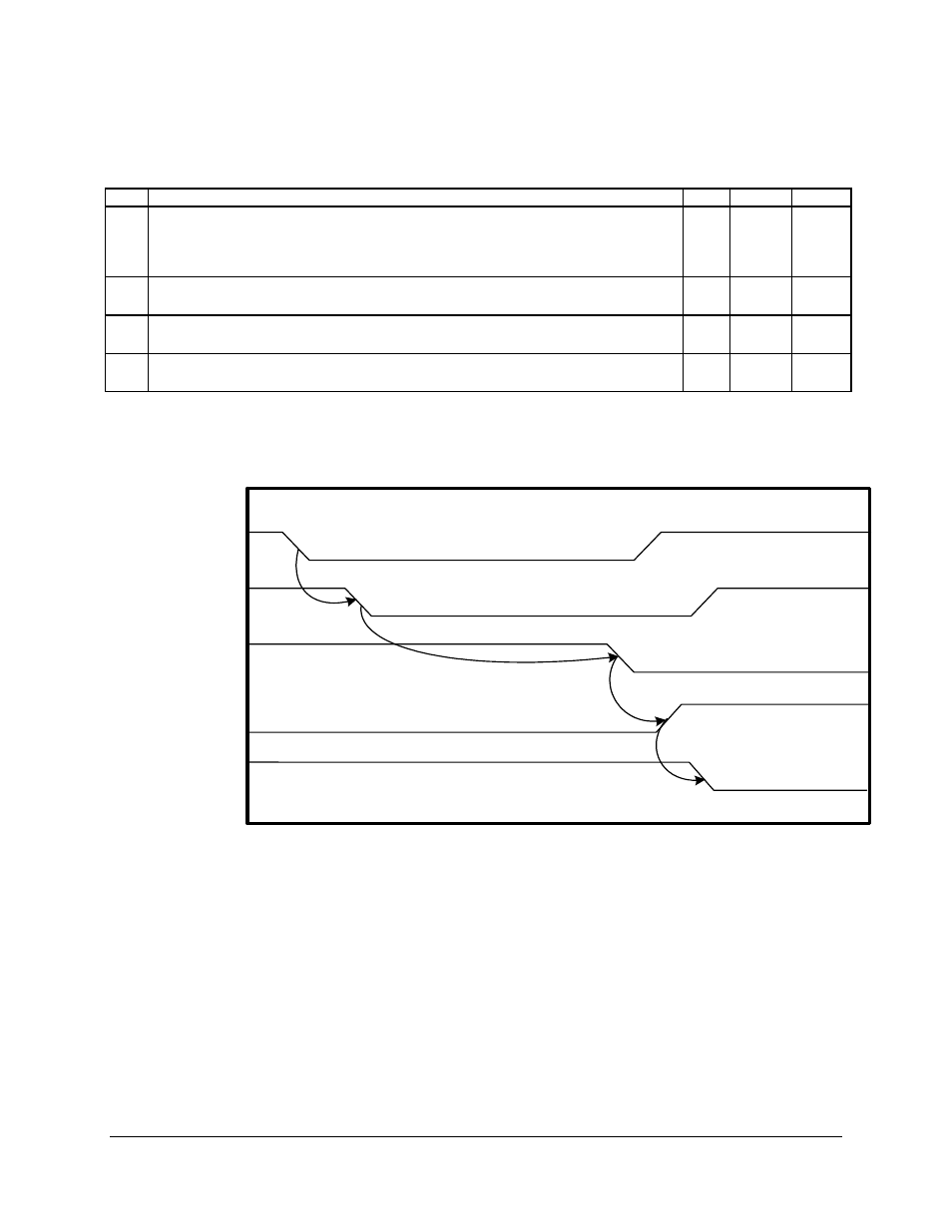
8.2.2 Power-Down
Sequence
POWER_SW_L
(I)
SM_PWRBTN_L
(O)
SLP_S5P_L
(I)
PS_ON_L
(O)
SYS_PWROK
(I)
t1
t2
t4
t3
Figure 15. Typical Power-Down Sequence